Acceleration sensor
- Summary
- Abstract
- Description
- Claims
- Application Information
AI Technical Summary
Benefits of technology
Problems solved by technology
Method used
Image

Examples
first preferred embodiment
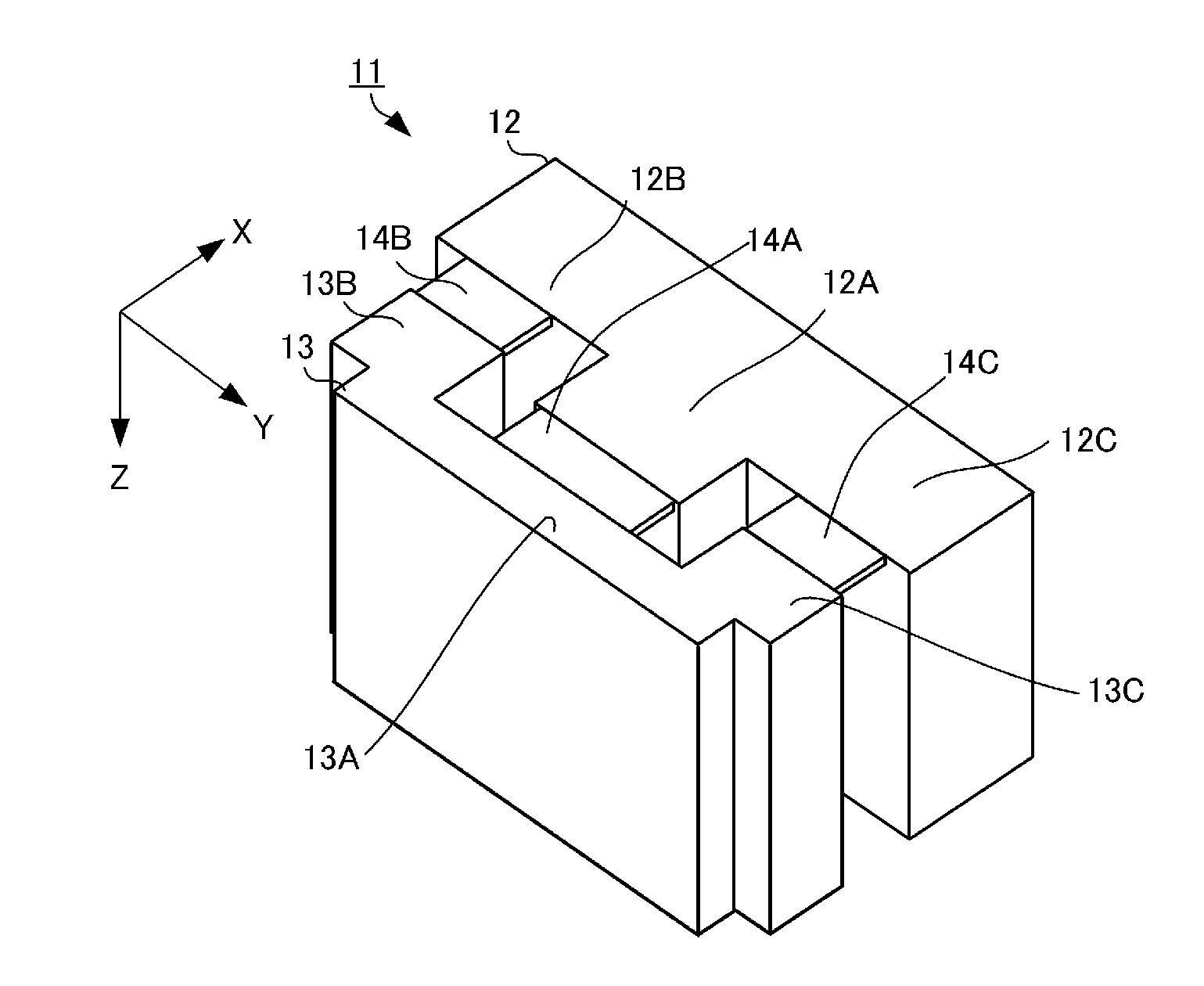
[0024]An acceleration sensor according to a first preferred embodiment of the present invention will be described with reference to FIGS. 1 to 4D. In the individual drawings, a Z axis along a thickness direction of the acceleration sensor, a Y axis along a planar direction of the acceleration sensor and orthogonal to the Z axis, and an X axis orthogonal to the Z axis and the Y axis are noted.
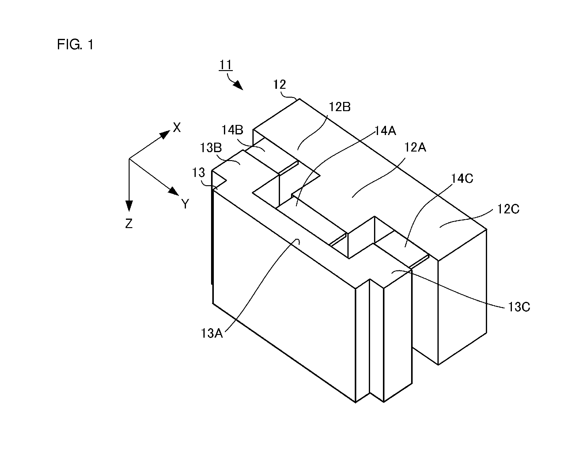
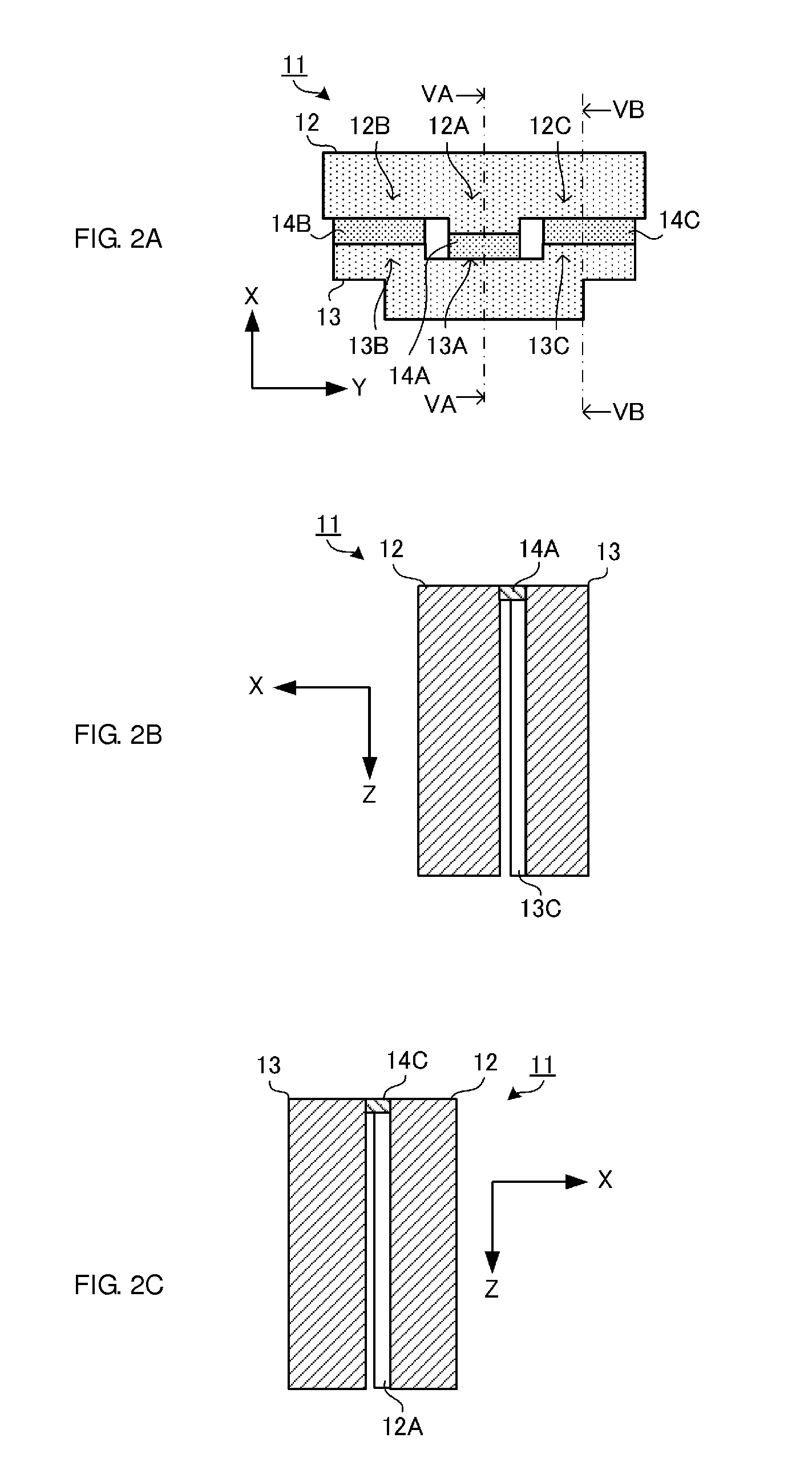
[0025]FIG. 1 is a perspective view illustrating an acceleration sensor 11 according to the first preferred embodiment of the present invention. FIG. 2A is a plan view along an X-Y plane of the acceleration sensor 11 when seen from the above. FIG. 2B is a cross-sectional view along an X-Z plane of the acceleration sensor 11 cut along a line VA-VA in FIG. 2A. FIG. 2C is a cross-sectional view along the X-Z plane of the acceleration sensor 11 cut along a line VB-VB in FIG. 2A.
[0026]The acceleration sensor 11 is a micro-electro-mechanical systems (MEMS) piezoresistive acceleration sensor preferably ...
second preferred embodiment
[0046]Next, a wiring structure in an acceleration sensor 21 according to a second preferred embodiment or the present invention will be described. The second preferred embodiment has the wiring structure different from that in the first preferred embodiment.
[0047]FIG. 5 is a plan view of the acceleration sensor 21 along the X-Y plane when seen from the above.
[0048]The acceleration sensor 21 includes the fixing portion 12, the weight portion 13, the detection beam 14A, the support beams 14B and 14C, the metal wirings 15B, 15C, 15D, and 15E, the piezoresistive elements 16A, 16B, 16C, and 16D, and the injection wirings 17 as the configuration same as that in the first preferred embodiment. Further, the acceleration sensor 21 includes a metal wiring 25 and injection wirings 27 as a configuration different from that in the first preferred embodiment.
[0049]The metal wiring 25 and the injection wirings 27 are electrically connected to each other, and are wired on a path so as to start from...
third preferred embodiment
[0051]Next, a wiring structure in an acceleration sensor 31 according to a third preferred embodiment of the present invention will be described. The third preferred embodiment has the wiring structure different from that in the second preferred embodiment.
[0052]FIG. 6 is a plan view of the acceleration sensor 31 along the X-Y plane when seen from the above.
[0053]The acceleration sensor 31 includes the fixing portion 12, the weight portion 13, the detection beam 14A, the support beams 14B and 14C, the metal wirings 15B, 15C, 15D, and 15E, the piezoresistive elements 16A, 16B, 16C, and 16D, and the injection wirings 17 as the configuration same as that in the second preferred embodiment. Further, the acceleration sensor 31 includes a metal wiring 35 and injection wirings 37 as a configuration different from that in the second preferred embodiment.
[0054]The metal wiring 35 and the injection wirings 37 are electrically connected to each other, and are wired on a path so as to start fro...
PUM
 Abstract
Description
Claims
Application Information
 - R&D
- Intellectual Property
- Life Sciences
- Materials
- Tech Scout
- Unparalleled Data Quality
- Higher Quality Content
- 60% Fewer Hallucinations
Browse by: Latest US Patents, China's latest patents, Technical Efficacy Thesaurus, Application Domain, Technology Topic, Popular Technical Reports.
© 2025 PatSnap. All rights reserved.Legal|Privacy policy|Modern Slavery Act Transparency Statement|Sitemap|About US| Contact US: help@patsnap.com