Safety cap for disposabsle syringe

a safety cap and syringe technology, applied in the field of safety caps for disposable syringes, can solve the problems of avoiding the use of safety syringes, nurses getting pricked by needles, university hospitals were pricked, etc., and achieve the effects of safe disposal, safe protection, and psychological stability

Inactive Publication Date: 2016-02-25
EUM NYEON SIK
View PDF1 Cites 0 Cited by
  • Summary
  • Abstract
  • Description
  • Claims
  • Application Information

AI Technical Summary

Benefits of technology

[0021]Also, preferably, the safety cap for a disposable syringe is formed in a color of any one of green, blue, yellow, grey and brown, which gives psychological stability.
[0022]According to the safety cap for the disposable syringe of the present invention, since the needle of the syringe is covered after use by inserting the needle from the lateral side through the cutout insertion portion formed in the safety cap, there are effects such that there is hardly any danger of accidents having fingers pricked by the needle, and the syringe can be safely disposed after use.
[0023]Also, since the safety cap is firmly fit into the syringe after use by the fitting groove formed in the safety cap, there is an effect that the needle can be safely protected by the safety cap even when the needle is separated from the syringe.
[0024]Also, because safety caps have a simple structure considering the property of disposable syr...

Problems solved by technology

Recently, there was an accident where a worker in a renowned national university hospital was pricked by a needle used on an HIV patient.
Also, oftentimes, there are accidents where nurses get pricked by a needle while disposing disposable syringes after use.
However, in practice, a considerable number of hospitals are avoiding the use of safety syringes for cost reasons.
For this reason, recently, more hospitals are giving orders to dispose syringes without covering the needle with a safety cap after use, and accordingly examples of secondary damages on workers such as cleaners are gradually increasing.
However, considering the cost of disposable syringes...

Method used


Image

  • Safety cap for disposabsle syringe
  • Safety cap for disposabsle syringe
  • Safety cap for disposabsle syringe

Examples


Embodiment Construction

[0035]Hereinafter, preferable embodiments of the safety cap for the disposable syringe according to an embodiment of the present invention are explained in detail with reference to the accompanying drawings. The present invention is not limited to such embodiments disclosed and may be modified variously in many different forms. The embodiments are provided to complete the disclosure of the present invention and to allow those having ordinary skill in the art to understand the scope of the present invention.

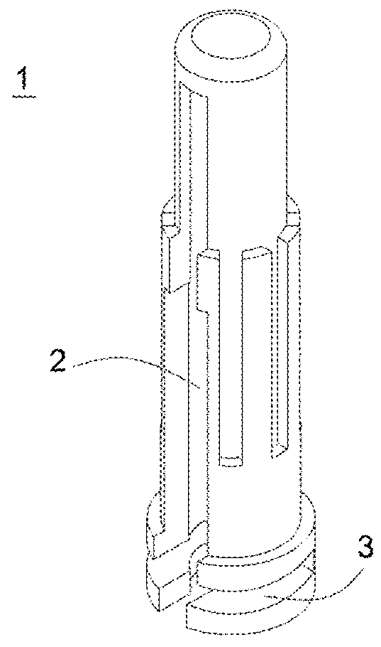
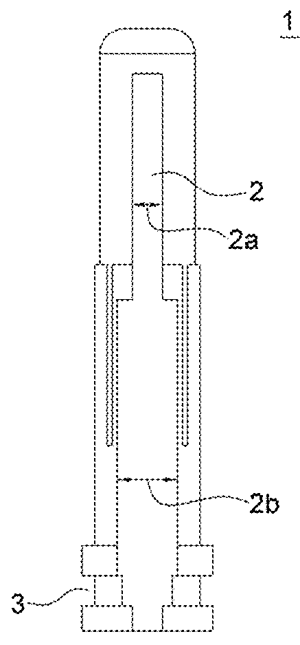
[0036]FIG. 1 is a perspective view of a safety cap for a disposable syringe according to an embodiment of the present invention, and FIG. 2 is a side view of a safety cap for a disposable syringe according to an embodiment of the present invention.

[0037]As illustrated in FIG. 1 and FIG. 2, the safety cap for the disposable syringe according to an embodiment of the present invention includes a cutout insertion portion 2 formed at the lateral side of the safety cap 1 and a fitting g...


PUM


Abstract

The present invention relates to a safety cap for a disposable syringe. In particular, the safety cap for covering a needle of the syringe has a cutout insertion portion formed at one side thereof and a ball provided at the inner upper end of the cutout insertion portion, so that it is possible to couple the needle of the syringe to the safety cap by inserting the needle into the ball and then rotating the needle about the ball. Further, the safety cap has a fitting groove formed at the lower end portion thereof, so that the safety cap can be coupled to and covered on the upper portion of the used syringe through the cutout insertion portion from the lateral side of the syringe, and be then forcibly coupled to the upper portion of the syringe through the fitting groove. Therefore, the safety cap can prevent a user, after using the syringe, from having a wound by being pierced by the needle or from being infected by germs through the wound.

Description

CROSS-REFERENCE TO RELATED APPLICATIONS[0001]This application claims priority to and the benefit of Korean Patent Application No. 10-2013-030761 filed in the Korean Intellectual Property Office on Mar. 22, 2013, the entire contents of which are incorporated herein by reference.TECHNICAL FIELD[0002]The present invention relates to a safety cap for a disposable syringe, and more specifically to a safety cap for a disposable syringe configured such that a cutout insertion portion is formed at one side of the safety cap covering a needle of the syringe, a ball is provided at the inner upper end of the cutout insertion portion so that a needle is coupled to the safety cap by inserting the needle into the ball and rotating it, and a fitting groove is formed at the lower end portion so that the safety cap is coupled to and covered on the upper portion of the syringe through the cutout insertion portion from the lateral side of the syringe after use and then is forcible coupled to the upper...

Claims


Application Information

Patent Timeline
IPC IPC(8): A61M5/32
CPCA61M5/3216A61M5/32A61M5/50
Inventor EUM, NYEON, SIK
Owner EUM NYEON SIK
Why Eureka
Try Eureka