Home electrical appliance

Inactive Publication Date: 2016-01-28
TOSHIBA LIFESTYLE PROD & SERVICES CORP
View PDF4 Cites 9 Cited by
  • Summary
  • Abstract
  • Description
  • Claims
  • Application Information

AI Technical Summary

Benefits of technology

[0005]The problem to be overcome by the present invention is providing a home electric appliance capable

Problems solved by technology

However, some users do not have access to the network or do not feel the need to connect to the network.
Thus, in a configuration designed to connect to the network as disclosed in patent doc

Method used


Image

  • Home electrical appliance
  • Home electrical appliance
  • Home electrical appliance

Examples


Example

[0010]A description is given hereinafter on one embodiment of a home electrical appliance with reference to FIGS. 1 to 3.

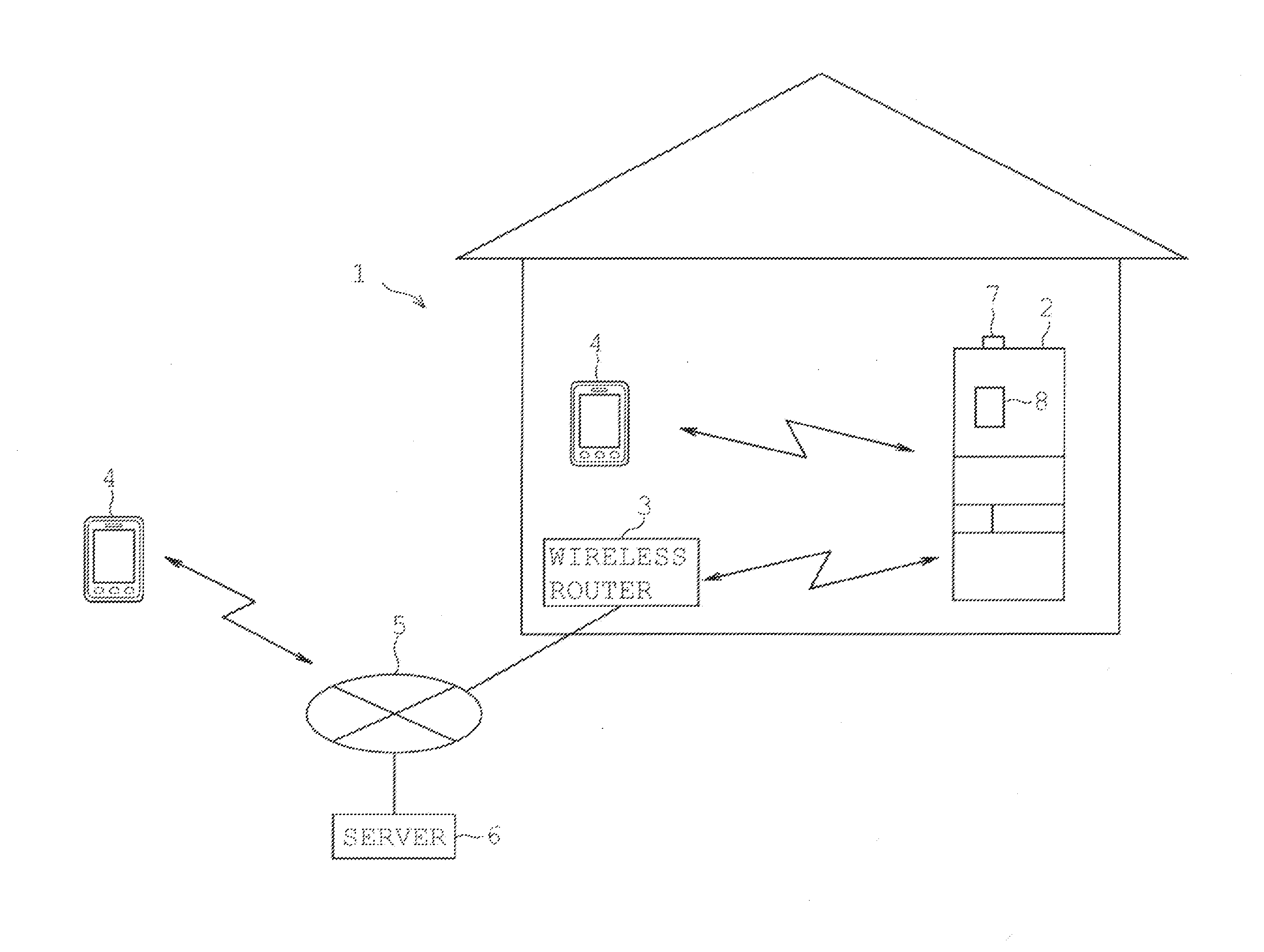
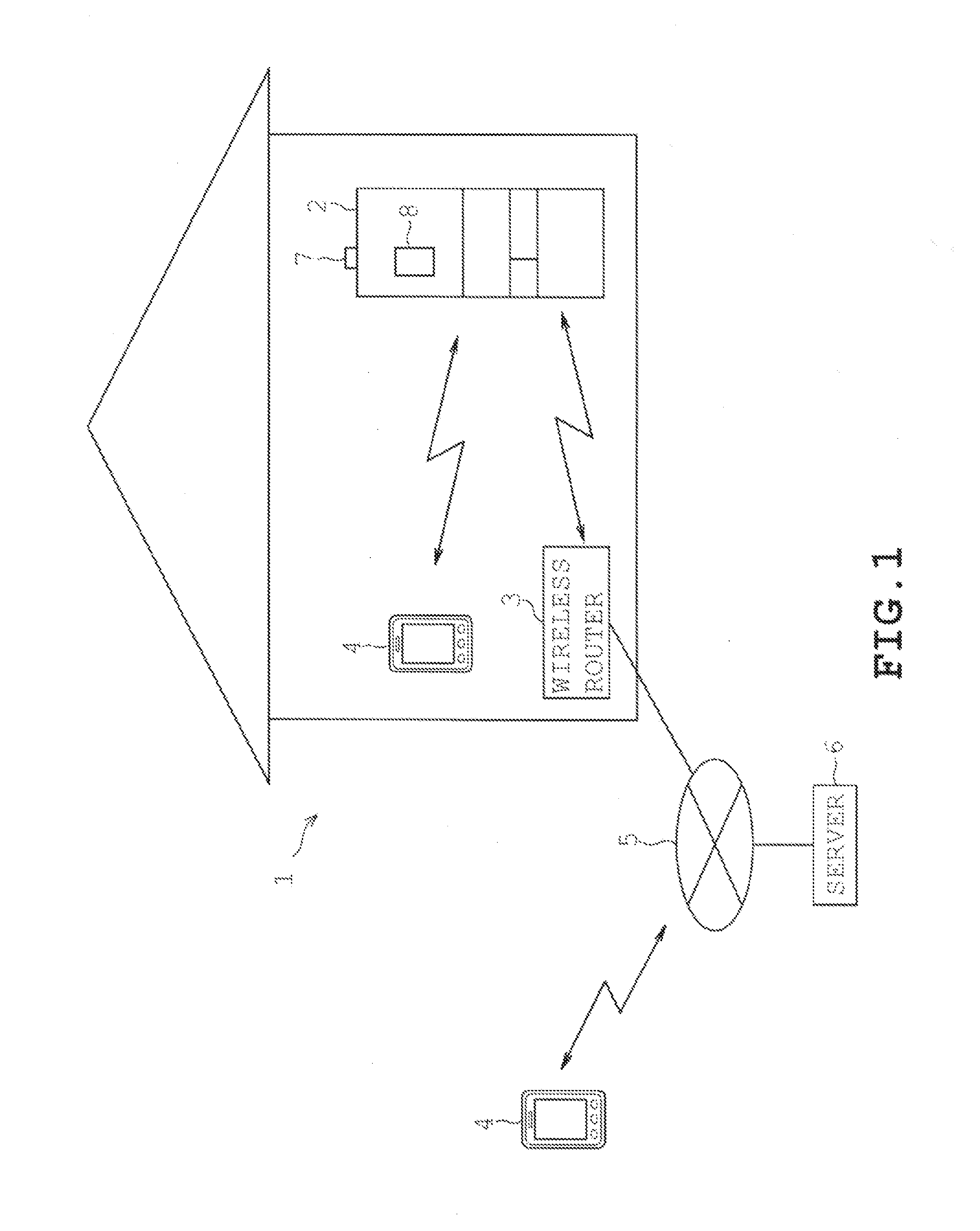
[0011]As illustrated in FIG. 1, home appliance network 1 employing the home electrical appliance of the present embodiment is provided with a refrigerator 2, a wireless router 3, a communication terminal 4, a network 5, and a sever 6. The refrigerator 2 is one example of a home electrical appliance. The wireless router 3 communicates with the refrigerator 2 through a wireless communication method. The communication terminal 4 communicates with the refrigerator 2 or the wireless router 3 through a wireless communication method. The wireless router 3 is connected to the network 5 which is in turn connected to the server 6. Further, the refrigerator 2 is capable of communicating with the communication terminal 4 over the network. The wireless router 3, the communication terminal 4, and the server 6 are examples of external devices recited in the claims.

[0012]The refr...


PUM

PropertyMeasurementUnit
Poweraaaaaaaaaa

Abstract

A refrigerator 2 serving as a home electrical appliance is provided with a functional portion 30 being provided with a communication device 7 (communication unit) configured to communicate with an external device such as a communication terminal 4 and a server 6 and operating with a prerequisite of using the communication device 7; a control panel 8 (setting specifying portion) configured to specify a setting to permit operation of the functional portion 30; and a main control portion 10 configured to limit operation of the functional portion 30 until the setting to permit operation of the functional portion 30 is specified from the control panel 8.

Description

TECHNICAL FIELD[0001]Embodiments of the present invention relates to a home electrical appliance.BACKGROUND[0002]Home electrical appliances are known in which a communication means is provided for communicating with external devices. Various forms of use are being suggested with an assumption that such home electrical appliances are connected to a network, etc (See for example, patent document 1).PRIOR ART DOCUMENTSPatent Document[0003]Patent Document 1: JP 2011-180868 ASUMMARY OF THE INVENTIONProblems to be Overcome by the Invention[0004]However, some users do not have access to the network or do not feel the need to connect to the network. Thus, in a configuration designed to connect to the network as disclosed in patent document 1, electric power is supplied to the communication means and the functional portion working by utilizing the communication means, resulting in meaningless consumption of electric power.[0005]The problem to be overcome by the present invention is providing...

Claims


Application Information

Patent Timeline
IPC IPC(8): G05B11/01H04W4/80
CPCG05B11/01H04W88/02H04W4/008F25D29/00G08C17/00H04W4/80
Inventor MARUTANI, YUUKIFURUTA, KAZUHIRO
Owner TOSHIBA LIFESTYLE PROD & SERVICES CORP
Why Eureka
Try Eureka