Transport device and method for operating the transport device

a technology of transport device and transport device, which is applied in the direction of conveyor parts, mechanical conveyors, non-mechanical conveyors, etc., can solve the problems of premature failure of said rollers, relatively high wear, and situations that can arise, and achieve the effects of facilitating a very compact and light design of the conveyor cart, energy saving, and minimal wear

Active Publication Date: 2016-01-14
SYNTEGON TECHNOLOGY GMBH
View PDF5 Cites 0 Cited by
  • Summary
  • Abstract
  • Description
  • Claims
  • Application Information

AI Technical Summary

Benefits of technology

[0003]The transport device according to the invention facilitates a very compact and light design of the conveyor cart. The light design is also associated with an energy efficient construction of the transport device because the smallest possible masses have to be moved. Because, according to the invention, the guiding rollers are no longer arranged offset to one another, the guiding rollers can roll optimally and therefore have a minimal amount of wear. In so doing, the service life of the guiding rollers increases; and at the same time, as few particles as possible are generated by abrasion. These advantages are achieved by a transport device comprising a stationary running rail which extends along a longitudinal axis and at least one cart which is guided on the running rail. The cart comprises guiding rollers. In particular, two guiding rollers are provided. The guiding rollers are arranged rotatably on the cart. The rotational axes of the guiding rollers are parallel to the height axis of the cart. The height axis is defined as perpendicular to the longitudinal axis. A transverse axis is defined as perpendicular to the longitudinal axis and perpendicular to the height axis. The rotational axis of each guiding roller intersects the same straight line. This straight line is defined as perpendicular to the longitudinal axis and extends in the transverse direction. From an ideal point of view, said straight line is aligned perpendicularly to the longitudinal axis. As soon as a small yaw moment occurs about the height axis, which is not immediately compensated, the imaginary straight line deflects somewhat. The crucial factor is, however, that provision is made according to the invention for a yaw moment about the height axis not to be stabilized by arranging the guiding rollers offset to one another. The transport device furthermore comprises a compensating device for compensating for the yaw moment of the cart about the height axis. This compensating device comprises multiple magnetic coils arranged along the running rail and at least two ferromagnetic or permanent magnetic counter elements which are arranged on the cart. Said counter elements are arranged on both sides of the running rail. In addition, the compensating device comprises a control device for controlling the magnetic coils. The magnetic coils are thereby actuated in such a manner that the counter elements are simultaneously pushed away from the running rail in the direction of the transverse axis. The two counter elements, which lie opposite one another, being pushed away from the running rail leads to a stabilization of the yaw moment and hence to a centered alignment of the cart. The magnetic forces utilized here increase inversely proportional to the square of the distance. That means that the further the cart is skewed by a yaw moment which arises, the stronger the corresponding force acts on the counter element approaching the running rail. A complicated control of the actuation of the magnetic coils is therefore not necessary because the arising force behaves inversely proportional to the square of the distance.

Problems solved by technology

Situations can, however, arise during the operation in which the conveyor carts yaw about the height axis thereof.
This leads to a transverse movement of the guiding rollers and thus to a relatively high wear and a premature failure of said rollers.
As a result, many particles are unnecessarily abraded which are especially undesirable in the area of food and pharmaceutical products or, respectively, food and pharmaceutical packagings.

Method used


Image

  • Transport device and method for operating the transport device
  • Transport device and method for operating the transport device
  • Transport device and method for operating the transport device

Examples


Embodiment Construction

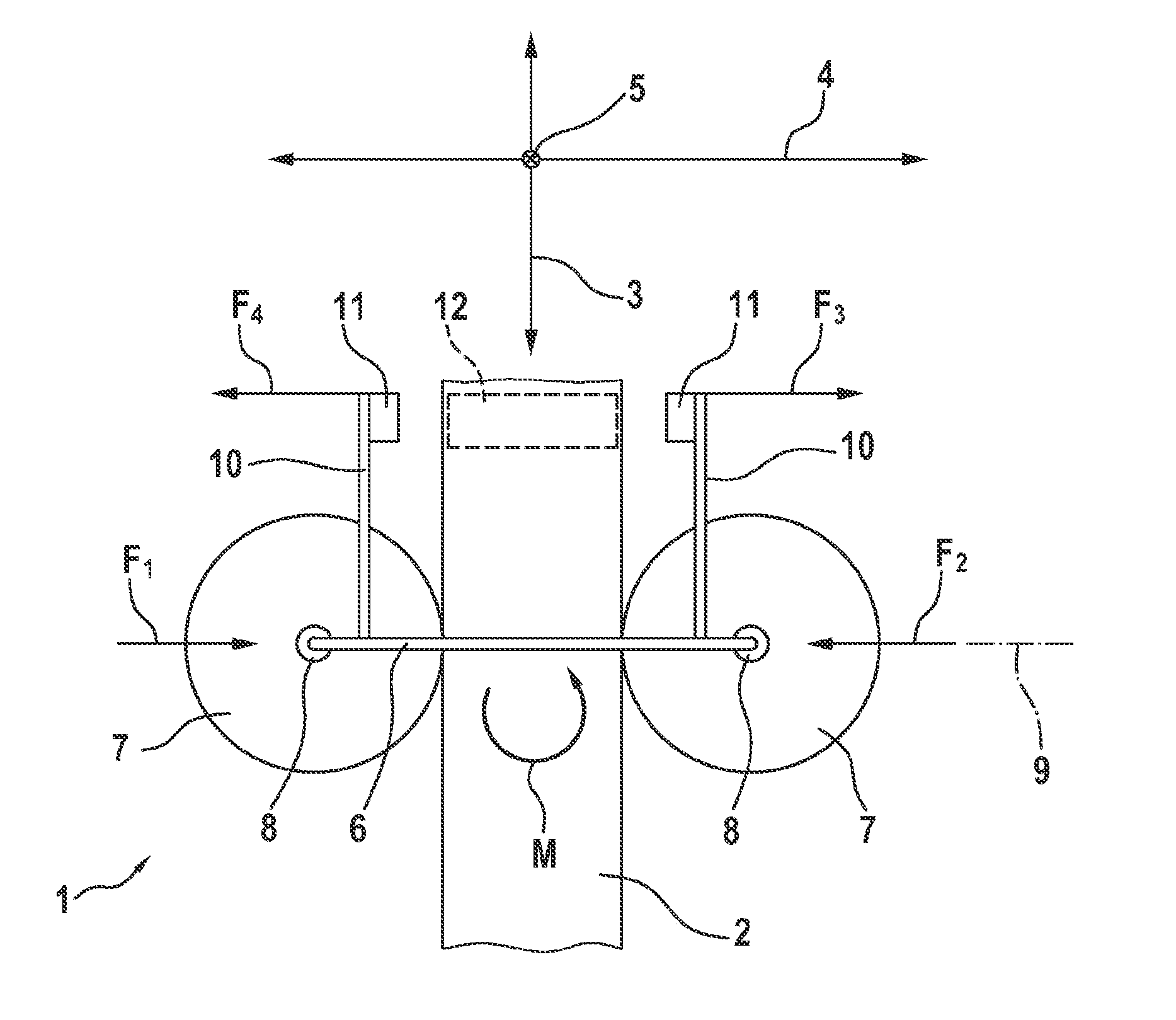
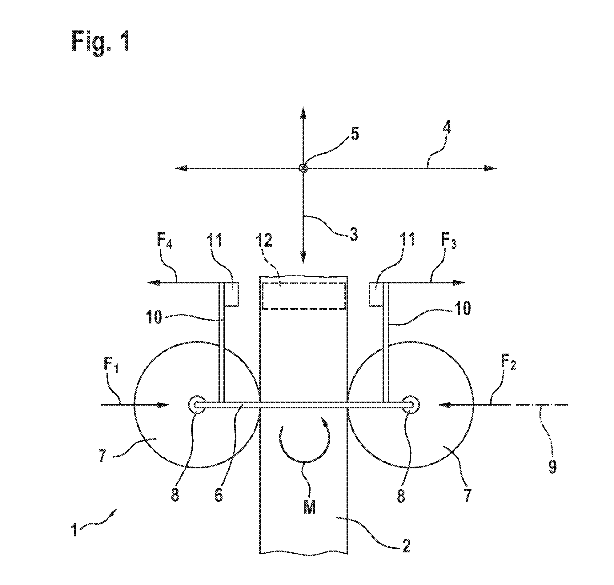
[0018]FIG. 1 shows the transport device 1 in a schematically simplified depiction. The transport device 1 comprises a stationary running rail 2. A cart 6 is guided on the running rail 2. The running rail 2 extends along a longitudinal axis 3. The cart 6 can be moved linearly in the direction of the longitudinal axis 3. A transverse axis 4 is defined as perpendicular to the longitudinal axis 3. A height axis 5 is defined as perpendicular to the transverse axis 4 and perpendicular to the longitudinal axis 3. The moment of the cart 6 about the height axis 5 is referred to as the yaw moment M.

[0019]The cart 6 has two guiding rollers 7. Each guiding roller 7 is mounted on the cart 6 so as to be rotationally movable about a rotational axis 8. The two rotational axes 8 intersect a straight line 9. The straight line 9 is defined as perpendicular to the longitudinal axis 3 when the cart is centrally aligned. By means of this aligned arrangement of the guiding rollers 7, the two forces F1 and...


PUM


Abstract

The invention relates to a transport device (1) for conveying a product, comprising a stationary running rail (2) which extends along a longitudinal axis (3); a cart (6) with a height axis (5) which is perpendicular to the longitudinal axis (3), said cart being guided on the running rail (2); guiding rollers (7) which are arranged on the cart (6), can be rotated about rotational axes (8) perpendicular to the longitudinal axis (3), and roll on the running rail (2), wherein the rotational axis (8) of each guiding roller (7) intersects the same straight line (9), which is perpendicular to the longitudinal axis (3); and a compensating device for compensating for a yaw moment (M) of the cart (6) about the height axis (5), comprising multiple magnetic coils (12) arranged along the running rail (2), at least two ferromagnetic or permanent magnetic counter elements (11) which are arranged on the cart (6) and which are arranged on both sides of the running rail (2), and a control device (18) for controlling the magnetic coils (12) such that the counter elements (11) can be simultaneously pushed away from the running rail (2) in the direction of a transverse axis (4), said transverse axis (4) being defined as perpendicular to the longitudinal axis (3) and perpendicular to the height axis (5).

Description

BACKGROUND OF THE INVENTION[0001]The present invention relates to a transport device for conveying a product as well as to a method for operating the transport device.[0002]Transport systems for conveying products are, for example, used in conveying applications of packaging machines and are known in different embodiments from the prior art. The German patent publication DE 10 2010 027 925 A1 describes, for example, a transport system in which a movable conveyor cart is moved by means of a linear motor drive device. The conveyor cart is thus designed in an articulated manner in order to be able to pass through smaller curve radii. Situations can, however, arise during the operation in which the conveyor carts yaw about the height axis thereof. In a schematically simplified depiction, FIG. 5 shows how this yaw moment M is stabilized in the prior art. According to FIG. 5, a conventional conveyor cart 106 comprises at least three guiding rollers 107 that are offset to one another. Said...

Claims


Application Information

Patent Timeline
Patent Type & Authority Applications(United States)
IPC IPC(8): B65G54/02
CPCB65G54/02B65G54/025
Inventor HANISCH, MARKUSVAN DE LOECHT, HEINRICH
Owner SYNTEGON TECHNOLOGY GMBH
Why Eureka
Try Eureka