
Climate control system for aircraft

a technology of climate control system and aircraft, which is applied in the direction of lighting and heating apparatus, heating types, energy-efficient board measures, etc., can solve the problems of both heating and ventilation loss of the system, the design of the outgoing and ingoing conduit is problematic, and the system is prone to damag

Inactive Publication Date: 2016-01-07
SMART CLIMATE SCANDINAVIA
View PDF64 Cites 10 Cited by
  • Summary
  • Abstract
  • Description
  • Claims
  • Application Information

AI Technical Summary

Benefits of technology

The present invention is a climate control system for aircraft that aims to address the problems associated with existing designs. The technical effects of the invention include reducing the impact of flight on the environment, providing more efficient and cost-friendly climate control for aircraft, and improving safety and accessibility for passengers and personnel. The invention also includes a more efficient design for cooling and heating the cabin of aircraft, with a focus on reducing fuel costs and environmental impact. Additionally, the invention addresses the need for a more efficient and flexible climate control system that can be adapted to different environmental conditions and can be used on both parked and flying aircraft.

Problems solved by technology

Furthermore, the system is only intended to cool air that is supplied to the aircraft's cabin.
For example, the design of the outgoing and ingoing conduits is problematic in regards to a winter climate.
Further, the climate control system is located on the roof of the structure causing problems with accessibility, for example in connection with repair, inspection, and the like.
The length of the conduit for air causes both heating and ventilation losses for the system.

Method used


Image

  • Climate control system for aircraft
  • Climate control system for aircraft
  • Climate control system for aircraft

Examples


Embodiment Construction

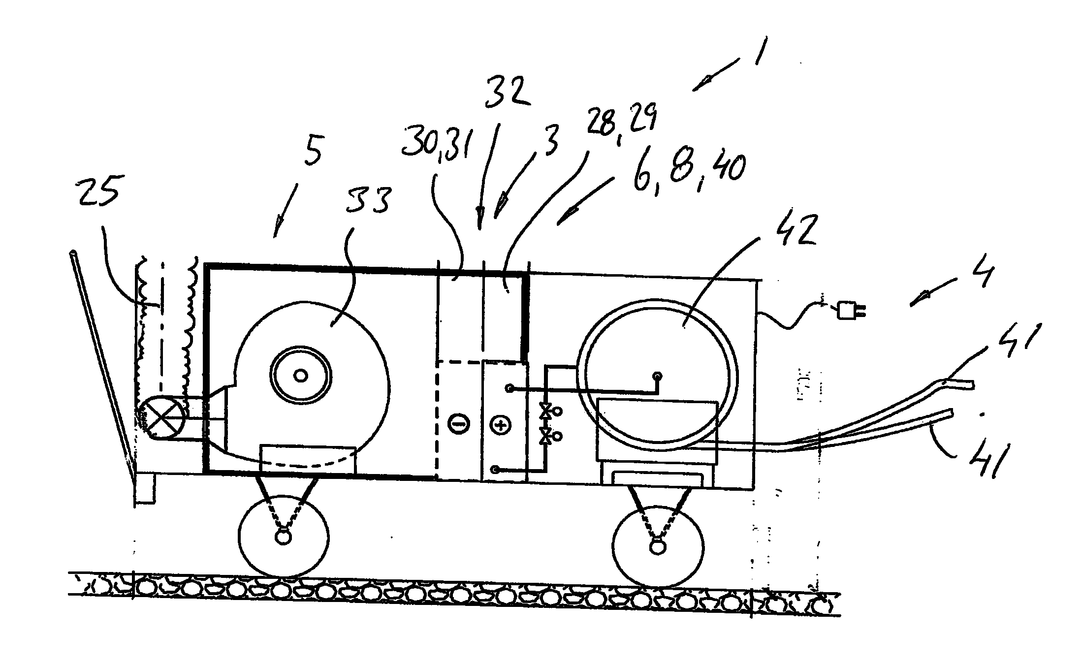
[0026]With reference to the figures, a climate control system 1 is shown that is for example intended to supply heated or cooled air to at least one aircraft 2 standing on the ground in accordance with the present patent application.

[0027]The climate control system 1 is comprised of at least one air handling unit 3 with which the supplied air to the aircraft is heated (warmed) or cooled. The climate control system 1 is further comprised of at least one subsystem 4 for supplying heated or cooled liquid to the air handling unit 3. The climate control system 1 is further comprised of at least one subsystem 5 for the transfer of heated or cooled air from the air handling unit 3 to the aircraft's 2 cabin. Subsystem 5 may also include a function for returning air from the aircraft's cabin to the climate control system with the intent to recover energy.

[0028]Referring to FIGS. 1A-1B and 4A-4D, an air handling unit 3 is shown which is placed on a transfer device 6 with which the air handlin...


PUM


Abstract

A climate control system (1), intended to be temporarily connected to at least one aircraft (2), when the aircraft is on the ground, with which handled air with at least one flexible conduit (23) is supplied to the aircraft's cabin from at least one air handling unit (3). The air handling unit (3) is comprised of at least one heating and cooling package (29) with which air to the cabin is heated or cooled and that the climate control system includes a transfer device (6) with which the air handling device may be moved in relation to the aircraft. The transfer device (6) is comprised of a telescopic boarding bridge (7). The climate control system (1) includes a subsystem for conveying heated or cooled fluid between the combined heating and cooling package (29) and a district heating network alternatively a network for district cooling, whose subsystem includes at least one flexible conduit (18) that includes at least one conduit for the input of fluid to the air handling unit and at least one conduit for return of fluid from the air handling unit.

Description

FIELD OF THE INVENTION[0001]The present invention concerns a variant of a climate control system for aircraft and the like in accordance with the claims.BACKGROUND OF THE INVENTION[0002]Flying has in today's society become a common way to travel quickly between different locations. Air travel and air transport give rise to many great possibilities but also give rise to a number of problems. One of the problems associated with air travel is that the air in the aircraft's cabin compartments is cooled or heated between flights in conjunction with the aircraft, for a shorter or longer period of time, being parked waiting for the next flight. A need to heat or cool the cabin air is usually present, especially during a long period of parking. The need to heat or cool the cabin air varies with the climate, temperature, where the plane is parked. In particularly hot or cold outside temperatures, the problems become challenging. In particularly hot or cold climate conditions, problems with c...

Claims


Application Information

Patent Timeline
IPC IPC(8): B64F1/227B64F1/305
CPCB64F1/305B64F1/364B64F1/362B64D2013/0618Y02T50/50B64D13/08
Inventor TENGMAN, ANDERS
Owner SMART CLIMATE SCANDINAVIA
Learn More