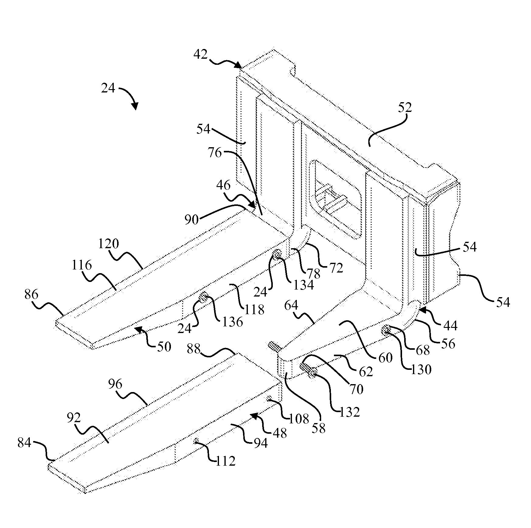
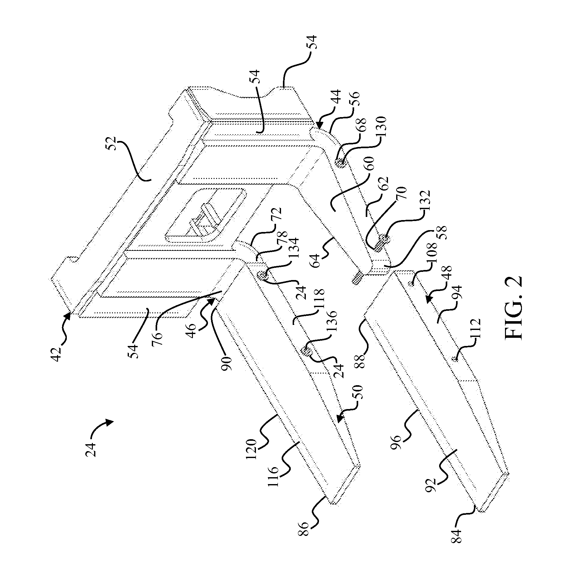
Fork assembly for lifting machines with interlocking tines
a technology of interlocking tines and forks, which is applied in the direction of load-engaging elements, lifting devices, transportation and packaging, etc., can solve the problems of increasing the probability of instability during the lift and transportation of goods, the bottom face and tip wear of the tines generally scraping against the floor surface, and the tendency of the tines to scrape against the floor
- Summary
- Abstract
- Description
- Claims
- Application Information
AI Technical Summary
Benefits of technology
Problems solved by technology
Method used
Image

Examples
Embodiment Construction
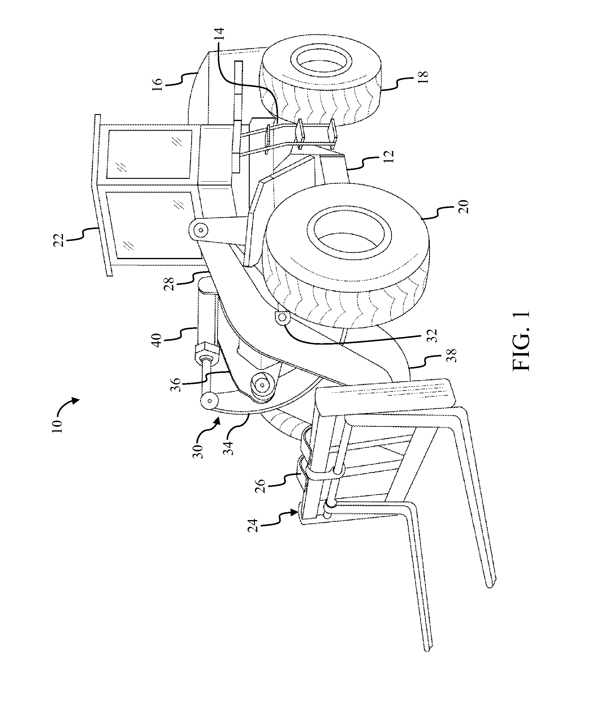
[0011]FIG. 1 illustrates an embodiment of a wheel loader machine 10. However, an application of the present disclosure is also envisioned for other conventionally available and applicable lifting machines, such as forklifts, block handlers, and the like. An extension of the aspects of the present disclosure is also contemplated for environments that apply structures and configurations similar to what has been disclosed here.
[0012]The wheel loader machine 10 includes a front-end frame 12, a rear-end frame 14, a body portion 16, rear wheels 18, front wheels 20, a cab 22, a fork assembly 24, and a coupler 26. The rear-end frame 14 supports the body portion 16, which houses an engine (not shown). The engine (not shown) drives the rear wheels 18. The body portion 16 is equipped with the cab 22 for an operator. The wheel loader machine 10 is hereafter referred to as the machine 10.
[0013]The front-end frame 12 is supported on the front wheels 20 that are turned by steering controls (not sh...
PUM
 Abstract
Description
Claims
Application Information
 - R&D
- Intellectual Property
- Life Sciences
- Materials
- Tech Scout
- Unparalleled Data Quality
- Higher Quality Content
- 60% Fewer Hallucinations
Browse by: Latest US Patents, China's latest patents, Technical Efficacy Thesaurus, Application Domain, Technology Topic, Popular Technical Reports.
© 2025 PatSnap. All rights reserved.Legal|Privacy policy|Modern Slavery Act Transparency Statement|Sitemap|About US| Contact US: help@patsnap.com