Light source, luminaire and surgical illumination unit

a technology of illumination unit and light source, which is applied in the field of light source, luminaire and surgical illumination unit, can solve the problem of insufficient contrast between colors, and achieve the effect of improving color contras

Active Publication Date: 2015-12-17
SIGNIFY HLDG BV
View PDF9 Cites 8 Cited by
  • Summary
  • Abstract
  • Description
  • Claims
  • Application Information

AI Technical Summary

Benefits of technology

[0005]It is an object of the invention to provide a light source having improved color contrast.

Problems solved by technology

Although the known light sources usually have a relatively good color rendering, often contrast between colors is not good enough.

Method used


Image

  • Light source, luminaire and surgical illumination unit
  • Light source, luminaire and surgical illumination unit
  • Light source, luminaire and surgical illumination unit

Examples


Embodiment Construction

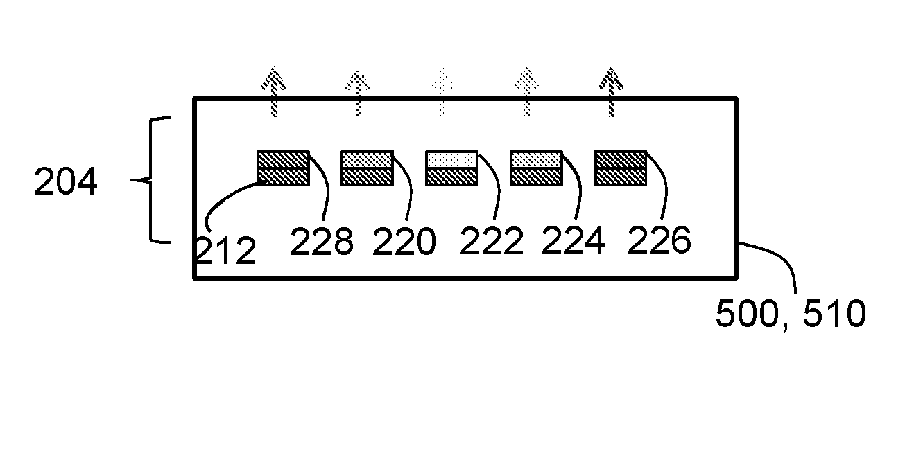
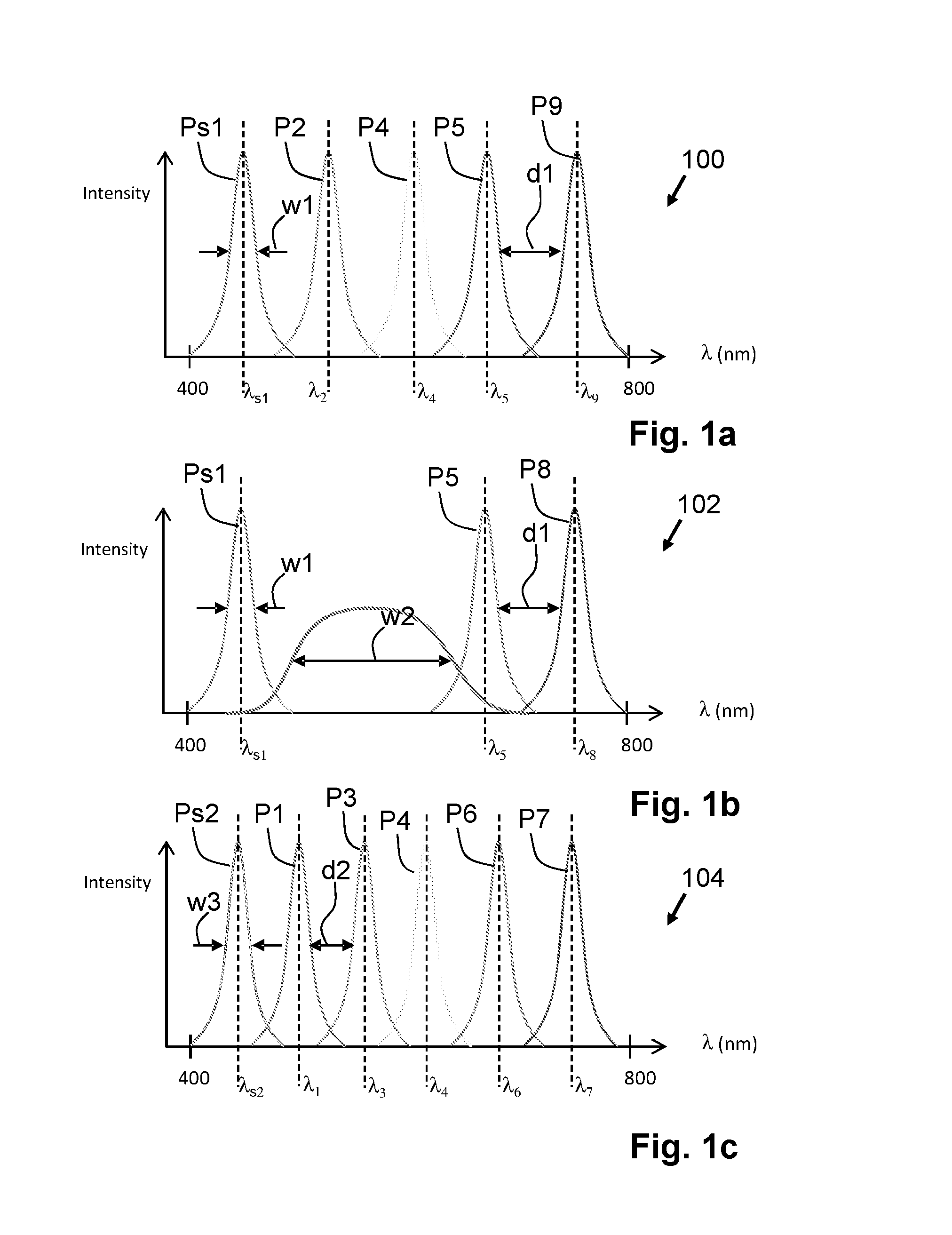
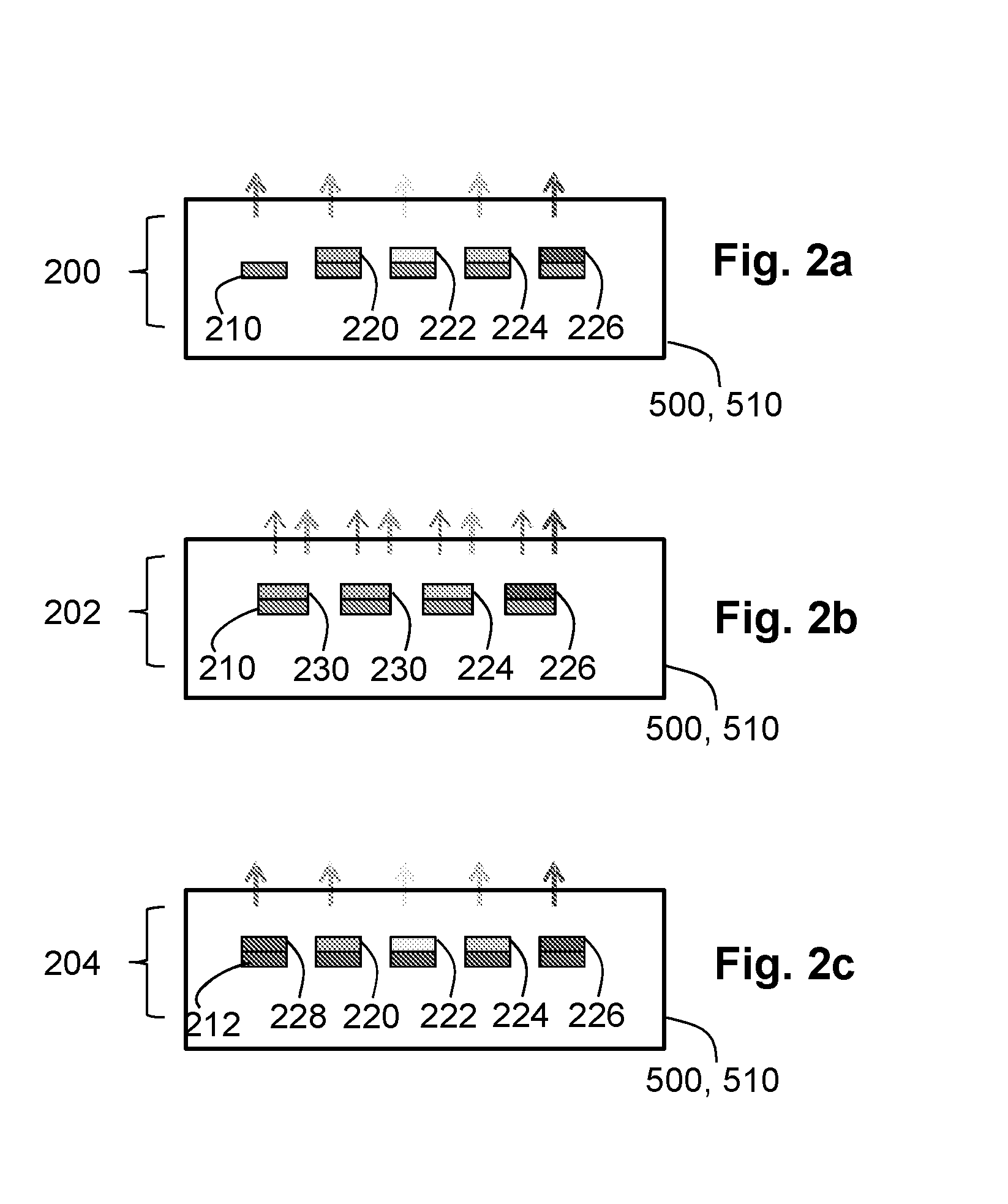
[0033]FIGS. 1a to 1c show different emission spectra 100, 102, 104 of a light source 500, 510 (see FIGS. 2 and 5) according to the invention. The light source 500, 510 according to the invention comprises a plurality of narrow-band light emitters 210, 220-228 (see FIG. 2). Such narrow-band light emitters 210, 220-228 comprise, for example, a light emitting device 210 emitting light in narrow spectral peak Ps1, Ps2, for example, solid state light emitters such as Light Emitting Diodes, Organic Light Emitting Diodes or Laser diodes; or the narrow-band light emitters 210, 220-228 comprise luminescent light conversion elements 220-228 which comprise luminescent materials emitting light in a narrow spectral peak P1-P9. A width w1, w3 of these narrow spectral peaks P1-P9 of the narrow-band light emitters 210, 220-228 is equal to or less than 40 nanometers and a distance d1, d2 between two neighboring spectral emission peaks P1-P9 is such that the two neighboring spectral emission peaks P1...


PUM

PropertyMeasurementUnit
full-width-half-maximumaaaaaaaaaa
wavelength rangeaaaaaaaaaa

Abstract

The Invention provides a light source, a luminaire and a surgical illumination unit in which two narrow-band light emitters both emit light in a narrow spectral peak having a full-width-half-maximum equal to or smaller than 40 nanometers. Both of the narrow-band light emitters have a different central emission wavelength within a blue color-range, within a green color range or within a red color-range. At least one of the two narrow-band light emitters comprises a luminescent material for generating the narrow spectral peak. The light source is further configured such that a distance between the narrow spectral peaks of the two narrow-band light emitters prevents overlap of the narrow spectral peaks. Due to the individual narrow spectral peaks, a color contrast within one of the color-ranges is significantly enhanced.

Description

FIELD OF THE INVENTION[0001]The invention relates to light source comprising at least two narrow-band emitters, each emitting light in a narrow spectral peak. The invention further relates to a luminaire and to a surgical illumination unit.BACKGROUND OF THE INVENTION[0002]Such light sources are known per se. They are used, inter alia, in luminaires for general lighting purposes, for example, for office lights, for shop lights or, for example, for shop window lights. These light sources are also used, inter alia, in special lighting applications such as hospital operating illumination units, for example, used during surgery, or special lighting applications used, for example, in graphical industry, printing industry, or specific shop light applications and advertisements.[0003]A current trend in light sources is to improve the efficiency of the light source, for example, by using semiconductor devices as light emitting devices. These semiconductor light emitting devices are, for exam...

Claims


Application Information

Patent Timeline
Patent Type & Authority Applications(United States)
IPC IPC(8): F21V9/16A61B19/00F21V9/08
CPCF21V9/16F21V9/08A61B19/5202A61B2019/521F21Y2101/02A61B2019/5204F21W2131/205A61B1/0638A61B1/0653A61B5/0075A61B90/30A61B2090/304A61B2090/309F21V7/30F21V9/06F21V9/32F21V9/45F21V13/08F21W2131/20F21Y2115/10
Inventor VAN BOMMEL, TIESHIKMET, RIFAT ATA MUSTAFA
Owner SIGNIFY HLDG BV
Why Eureka
Try Eureka