
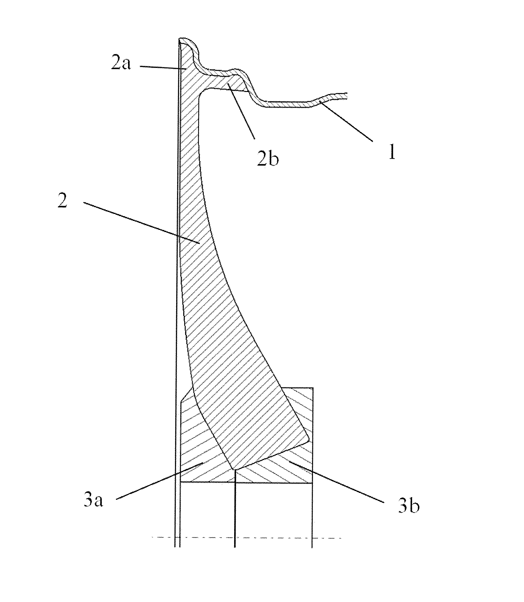
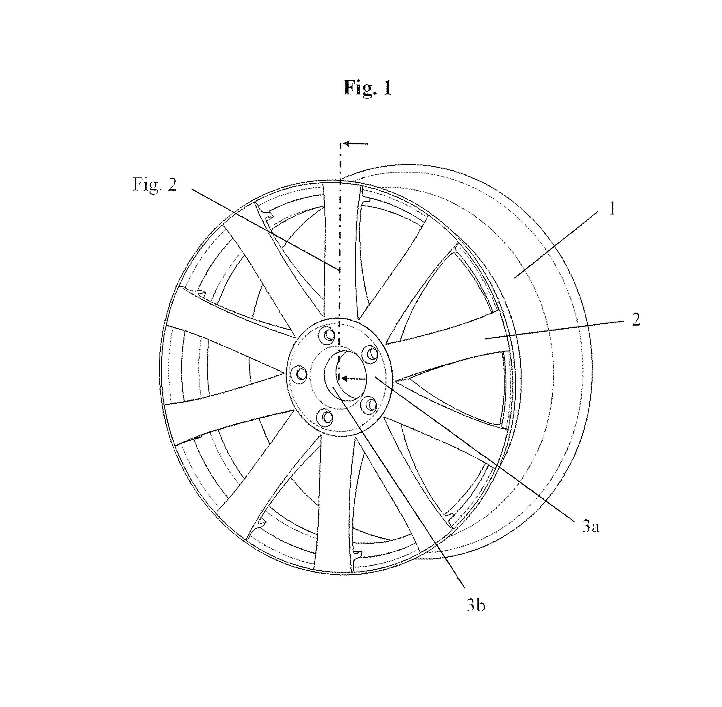
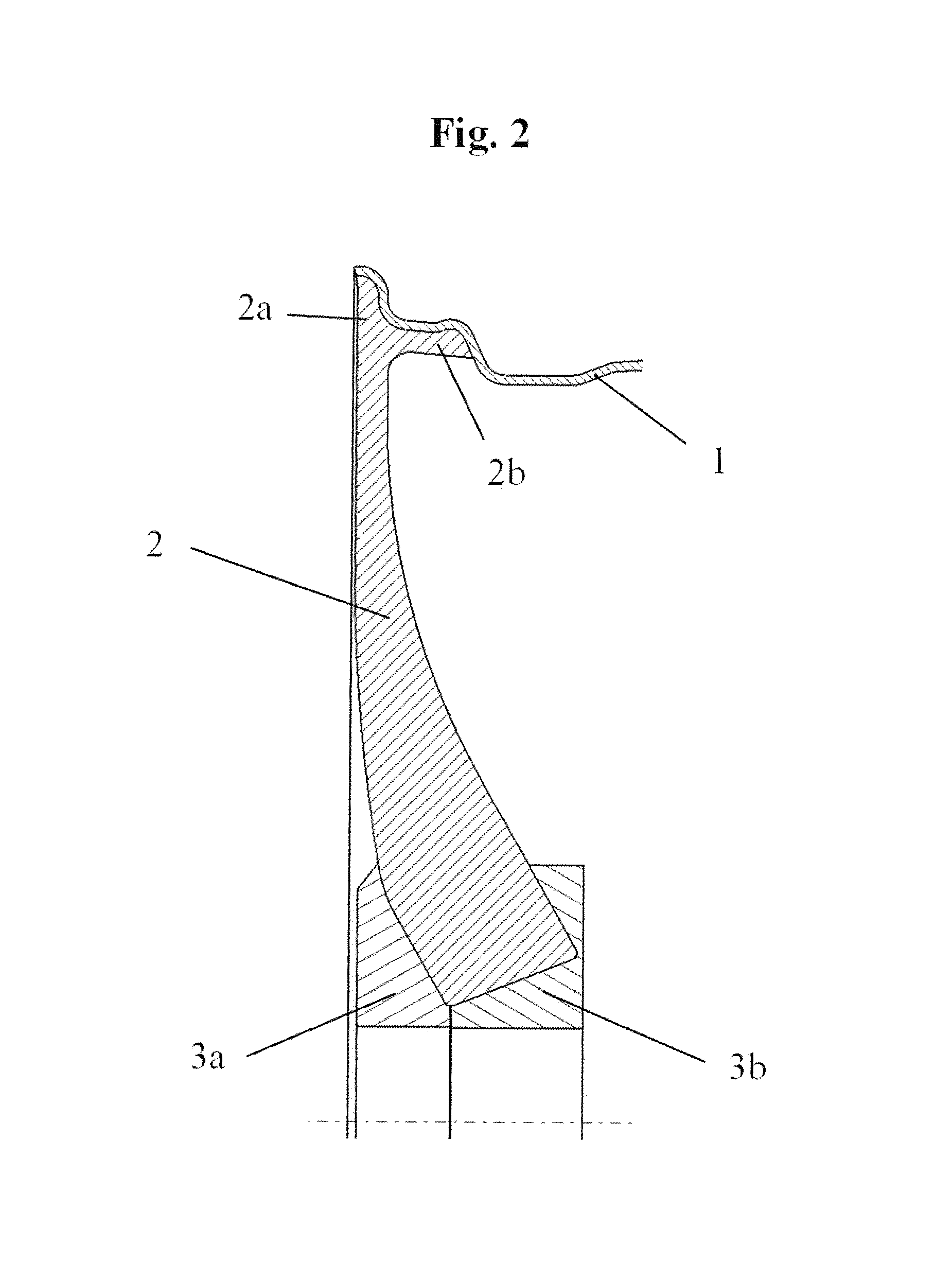
Wheel spider with assembled spoke elements and connection of wheel spider to rim well

a technology of spoke elements and wheel spiders, applied in the field of wheels, can solve problems such as not pure decorative elements, and achieve the effect of high design freedom of spoked wheels and high weight-saving potential of wheel spiders

Active Publication Date: 2015-12-17
THYSSENKRUPP CARBON COMPONENTS
View PDF10 Cites 16 Cited by
  • Summary
  • Abstract
  • Description
  • Claims
  • Application Information

AI Technical Summary

Benefits of technology

The present invention is related to a wheel construction for vehicles that includes hub parts and spoke elements. The hub parts are made of fiber-reinforced material, preferably the same material used for the rim or spoke elements. The hub parts have bolt holes for fastening bolts of the wheel and may have pins to support transmission of radial forces onto the spokes. The spoke elements have moldings in the hub area that transmit contact forces and absorb or transmit the forces occurring at the abutting surfaces of the spoke elements. The wheel construction according to the present invention is advantageous in achieving high weight-saving potential and offers a high design freedom for spoked wheels.

Problems solved by technology

Thus, they are not pure decorative elements.

Method used


Image

  • Wheel spider with assembled spoke elements and connection of wheel spider to rim well
  • Wheel spider with assembled spoke elements and connection of wheel spider to rim well
  • Wheel spider with assembled spoke elements and connection of wheel spider to rim well

Examples


exemplary embodiment 1

According to FIG. 1, FIG. 2, FIG. 3, FIG. 4(a-c), FIG. 5, and FIG. 6

[0039]In the first exemplary embodiment, the wheel spider is made up of individual radial spoke elements (2), which are assembled in the area of the wheel hub. The spoke elements which are assembled over circumferentially directed connecting surfaces in this case form the wheel hub. The molding of the spokes takes place in advance, for example, by means of TFP technology (Tailored Fiber Placement Technology), with which the individual textile strands are made up of a plurality of already dimensioned fiber layers and thus, the unconsolidated final contour can be produced, taking into account the later spoke shape. In this connection, the stratification of the fiber layers may take place differently, for example, in the axial (FIG. 4b) direction or in the circumferential direction (FIG. 4c). The spoke ends connected to the rim well (1) have two separate textile strands, which, on the one hand, run up to the rim flange...

exemplary embodiment 2

According to FIG. 7, FIG. 8

[0040]The second exemplary embodiment differs from the first one to the effect that the individual spoke elements produce a positive-locking, undercut connection to the entire well of the rim well. Here, the spoke end (2b) running to the well is adapted, so that the wall thickness from the rim flange area up to the beginning of the rim well increases markedly and the strap forming the undercut is adapted corresponding to the rim well. This spoke connection makes possible a simplification of the mold by no inserter tool being needed for the undercut formation. The spoke ends (2b) enclosing the rim well are therefore inserted into grooves provided for this after mounting the inner mold. The rim well contour necessary for the braiding process is therefore formed by the inner and outer molds as well as the folded-over spoke ends.

exemplary embodiment 3

According to FIG. 9, FIG. 10

[0041]FIG. 10 schematically shows the joining zones (9) between the individual spoke elements (2), wherein in this case the spoke elements differ in their radial length in the direction of the wheel central axis. Every other spoke thus has a type of recess in the radial direction, after which a stepped wheel hub area forms. The force application elements (3a, 3b) are designed such that axial bulges mesh with the recesses and thus a non-rotatable connection is produced between the spoke elements and the force application elements and rotational forces can be transmitted better. The spoke elements (2) are held in the axial direction by means of the hub parts (3a and 3b).


PUM

PropertyMeasurementUnit
areaaaaaaaaaaa
shapeaaaaaaaaaa
absorbing forcesaaaaaaaaaa

Abstract

A wheel includes a rim having a rim well and rim flanges, a hub, and at least three spoke elements. Each spoke element forms at least one spoke between the hub and the rim. The spoke elements are fastened to an inside of the rim in a form-closed manner or a form-closed and bonded manner. In the hub region, the spoke elements are supported on each other in a circumferential direction at abutting surfaces designed therefor. A method for producing the wheel is provided.

Description

CROSS REFERENCE TO RELATED APPLICATIONS[0001]This application is a United States National Phase Application of International Application PCT / EP2014 / 051543 filed Jan. 27, 2014 and claims the benefit of priority under 35 U.S.C. §119 of German Patent Application 10 2013 201 842.8 filed Feb. 5, 2013, the entire contents of which are incorporated herein by reference.FIELD OF THE INVENTION[0002]The subject of the present patent application is a wheel, preferably for motor vehicles, with spokes, wherein the spokes border directly on one another in the hub area in the circumferential direction and are fixed by two hub parts in the axial direction. On the rim side, the spokes are fastened to the inside (the side facing the axle) of the rim well. Furthermore, a process for manufacturing the wheel made of fiber composite material according to the present invention is disclosed.BACKGROUND OF THE INVENTION[0003]There are a variety of wheel constructions for motor vehicles, especially automobiles...

Claims


Application Information

Patent Timeline
Patent Type & Authority Applications(United States)
IPC IPC(8): B60B3/10B60B3/04B29C70/06B29C70/30
CPCB60B3/10B29C70/30B60B3/041B29C70/06B60B2360/341B29K2105/253B60B2900/311B60B2310/204B60B2310/241B29L2031/32B60B2900/111B29C70/345B29D99/0032B60B1/14B60B5/02B29L2031/322B29C70/302Y02T10/86
Inventor WERNER, JENSKOHLER, CHRISTIANBARTSCH, ANDREDRE LER, MICHAELMAKE, SANDRO
Owner THYSSENKRUPP CARBON COMPONENTS
Learn More