Segmented core and method for molding an impeller

a technology of segmental core and molding method, which is applied in the direction of domestic articles, domestic applications, applications, etc., can solve the problem of not being able to mold the different three-dimensional segments in one-piece, and achieve the effect of high design freedom

Active Publication Date: 2018-07-10
GRUNDFOS HLDG
View PDF10 Cites 10 Cited by
  • Summary
  • Abstract
  • Description
  • Claims
  • Application Information

AI Technical Summary

Benefits of technology

[0007]Therefore, the present invention is based on the object to provide a segmented core to be used for molding an impeller, and a method for molding an impeller which allow an impeller to be mode by a MIM process and still allowing for a high design freedom to realize complex shapes.
[0008]According to the present invention, a segmented core for molding of an impeller, especially a pump impeller, is provided comprising at least three segments, all segments having the same form and each segment having connecting means (connecting devices comprised of connecting features as part of the segment shape) for connecting the segment with the adjacent segments. Specifically, by segmenting the core into connectable elements, it is possible to have free access to each side of each segment during the molding process. This is necessary for forming the impeller since it is technically impossible to mold the different three dimensional segments in one-piece. By providing a segmented core for molding on impeller, a complex geometry may be implemented and a great design freedom is thus provided.

Problems solved by technology

This is necessary for forming the impeller since it is technically impossible to mold the different three dimensional segments in one-piece.

Method used


Image

  • Segmented core and method for molding an impeller
  • Segmented core and method for molding an impeller
  • Segmented core and method for molding an impeller

Examples


Embodiment Construction

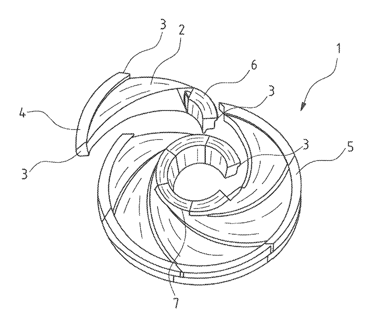
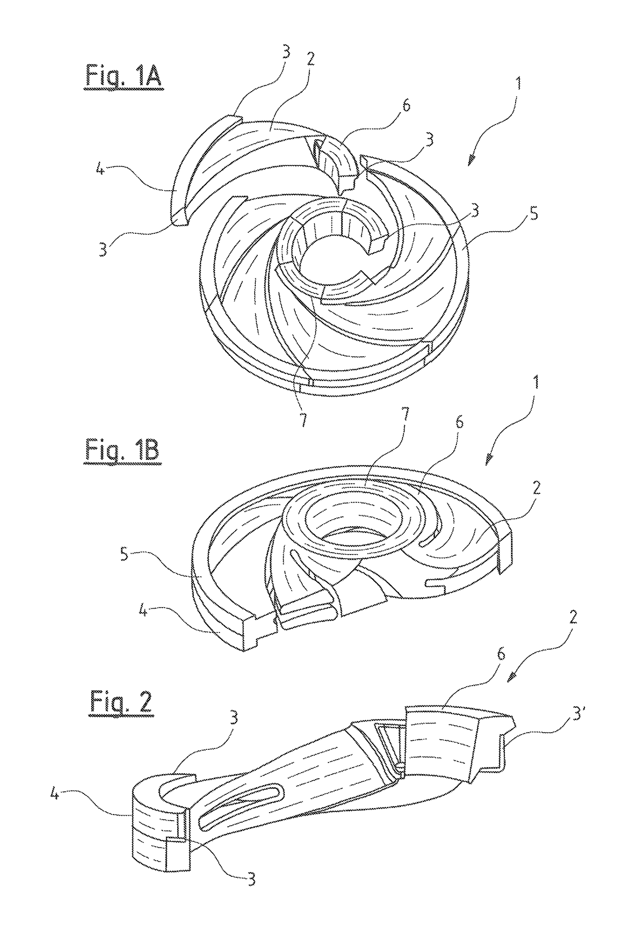
[0033]FIGS. 1A and 1B are respective views of a segmented core 1 according to on embodiment of the invention. Specifically, FIG. 1A is a perspective view of the segmented core 1 with one segment 2 removed and FIG. 1B is a partial sectional view of the segmented core 1. As can be seen in FIG. 1A, the segmented core of the embodiment consists of six single segments 2 which are connected to each other by connecting means or connecting device 3. Specifically, there are respectively provided two first connecting means 3, arranged at on outer portion 4 of each segment 2, whereby the outer portions 4 of all segments 2 together form on outer ring 5, and there is respectively provided one second connecting means or connecting device 3′ provided at on inner portion 6 of each segment 2 whereby the inner portions 6 of all segments 2 together form on inner ring 7. The connection means 3, 3′ of the segments 2 are formed as self-locking parts of the inner and outer rings 5, 7 of the core 1. In the...


PUM

PropertyMeasurementUnit
energyaaaaaaaaaa
volumeaaaaaaaaaa
thermoplasticaaaaaaaaaa

Abstract

A segmented core (1) for molding of an impeller (12), especially a pump impeller, includes at least three segments (2). All of the segments (2) have the same form and each segment (2) has connecting devices (3, 3′) for connecting the segment (2) with the adjacent segments (2). A method for molding an impeller (12) includes the steps of: providing a molding tool (14), providing a core (1) including at least three identical segments (2), which include the connection portions (3, 3′) for connecting the segment (2) with the adjacent segments (2); assembling of the core (1); placing the core (1) in the molding tool (14); molding the impeller (12), ejecting the core (1) and the impeller (12) out of the molding tool (14); and removing the core (1) from the impeller (12).

Description

CROSS REFERENCE TO RELATED APPLICATIONS[0001]This application is a United States National Phase Application of International Application PCT / EP2014 / 052142 filed Feb. 4, 2014 and claims the benefit of priority under 35 U.S.C. § 119 of European Patent Application EP 13 155 624.3 filed Feb. 18, 2013, the entire contents of which are incorporated herein by reference.FIELD OF THE INVENTION[0002]The invention relates to a segmented core for molding of on impeller and a method for molding on impeller.BACKGROUND OF THE INVENTION[0003]In prior art, impellers ore used for a variety of applications. For example, impellers may be used as a rotating component in pumps as, e.g., centrifugal pumps, for transferring energy from a motor that drives the pump to a fluid being pumped. Usually, impellers are made from metal and are configured as short cylinders with an inlet for incoming fluid, vanes for pushing the fluid radially, and a bore to accept a drive shaft.[0004]Small impellers nowadays are ma...

Claims


Application Information

Patent Timeline
Patent Type & Authority Patents(United States)
IPC IPC(8): B22C9/10B29C45/40B29C33/76B29C33/00B22F7/06B22F3/22F04D29/22B29L31/08
CPCB22C9/103B22F3/225B22F7/06B29C33/0033B29C45/40F04D29/2222B29C33/76B29L2031/08B29K2859/00B29K2905/06B22C9/10
Inventor VESTERMARK VAD, MARTIN
Owner GRUNDFOS HLDG
Why Eureka
Try Eureka