Flow path member, liquid ejecting head and liquid ejecting apparatus

Active Publication Date: 2015-12-10
SEIKO EPSON CORP
View PDF2 Cites 5 Cited by
  • Summary
  • Abstract
  • Description
  • Claims
  • Application Information

AI Technical Summary

Benefits of technology

The invention relates to a liquid ejecting apparatus with a configuration that allows for the efficient space usage and easy positioning of nozzle rows. Additionally, the invention includes a filter that can be placed on the liquid ejecting surface, which makes it possible to have a compact device. The air bubble chamber is also designed to prevent clogging, even if there is a variation in the liquid consumption amount between the filter chambers. Overall, this invention provides a liquid ejecting apparatus with improved space utilization, easy positioning, and prevention of clogging.

Problems solved by technology

In addition, there is a problem in that a large amount of air bubbles may clog the filter depending on the variation of a liquid consumption amount in a filter chamber; however, the examination of arrangement of a flow path which is not affected even in a case where such a variation of the liquid consumption amount is generated in the filter chamber was not performed.
In addition, the fixing member which is formed of the film has compliance, but the flow path wall portion can reduce the compliance.
Further, since the middle wall portion and the outer wall portion are discontinuous, the air bubbles are not prevented from moving from the filter chamber to the air bubble chamber.

Method used


Image

  • Flow path member, liquid ejecting head and liquid ejecting apparatus
  • Flow path member, liquid ejecting head and liquid ejecting apparatus
  • Flow path member, liquid ejecting head and liquid ejecting apparatus

Examples


first embodiment

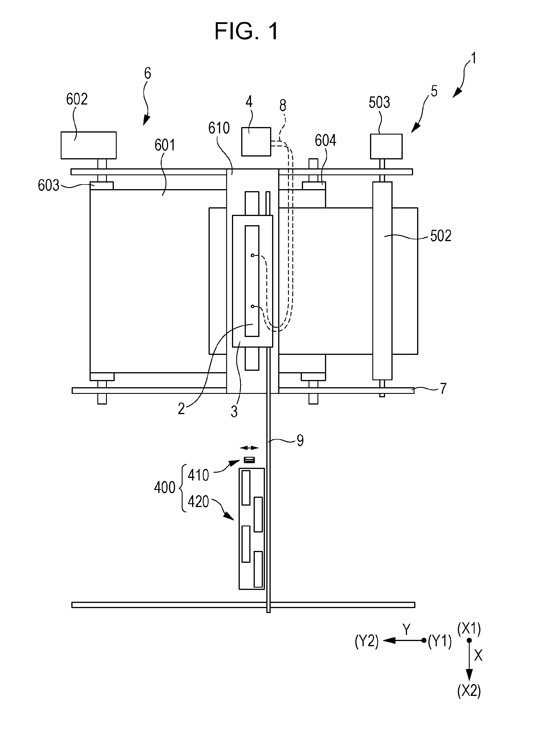
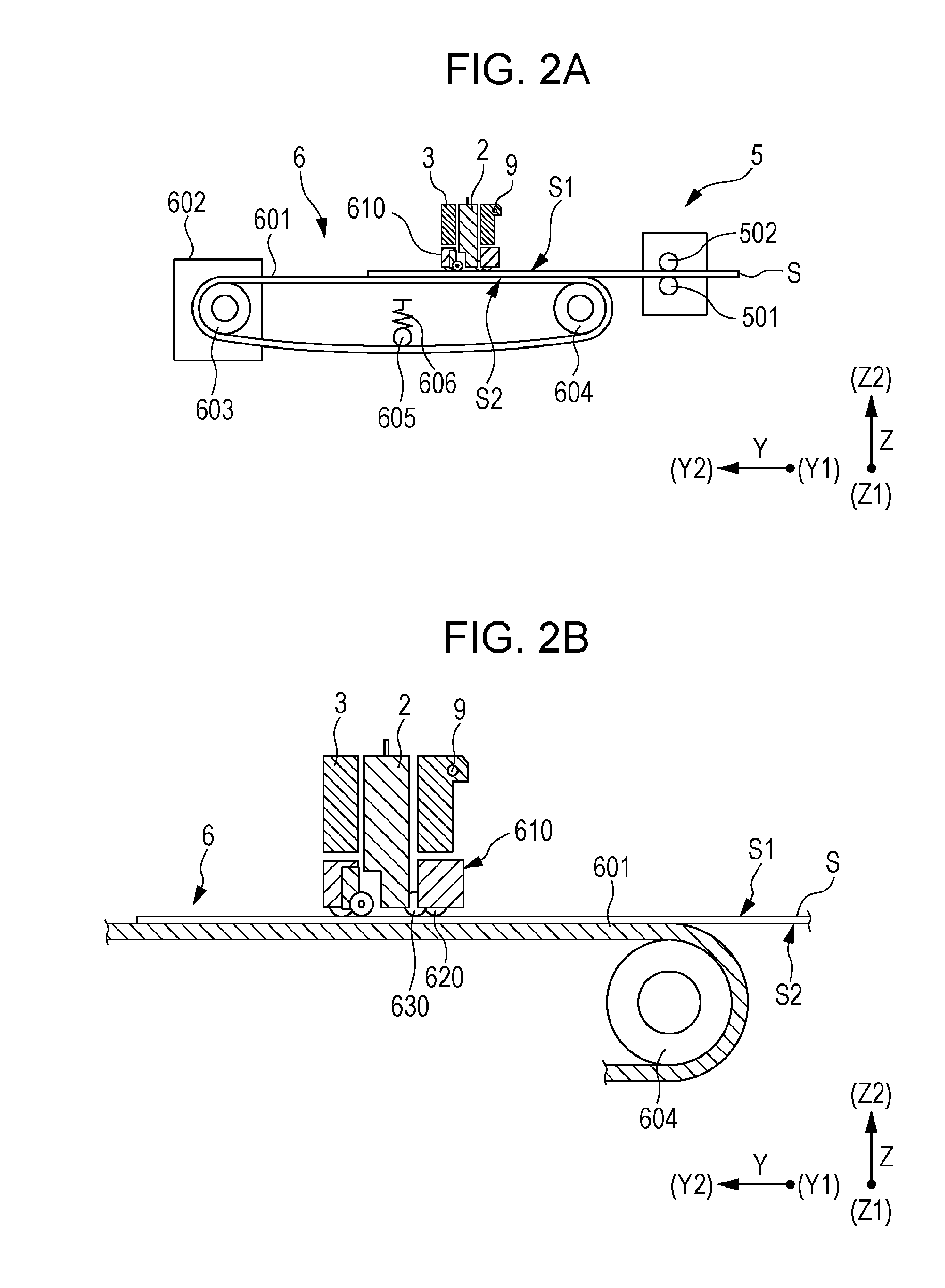
[0067]Detailed description will be made based on the embodiments of the present invention. An ink jet type recording head is an example of a liquid ejecting head, and is simply referred to as a recording head in some cases. An ink jet type recording apparatus is an example of the liquid ejecting apparatus. FIG. 1 is a top view schematically illustrating the ink jet type recording apparatus according to the first embodiment, and FIG. 2A is a side view of the ink jet type recording apparatus and FIG. 2B is an enlarged view of the side view.

[0068]The ink jet type recording apparatus 1 is a so-called ink jet type recording apparatus 1 which performs a printing process by transporting a recording sheet S which is an ejecting object medium.

[0069]A transporting direction of the recording sheet S is referred to as a second direction Y, in an in-plane direction of a landing surface S1 on which ink of the recording sheet S lands, and a direction orthogonal to the second direction Y is referre...

second embodiment

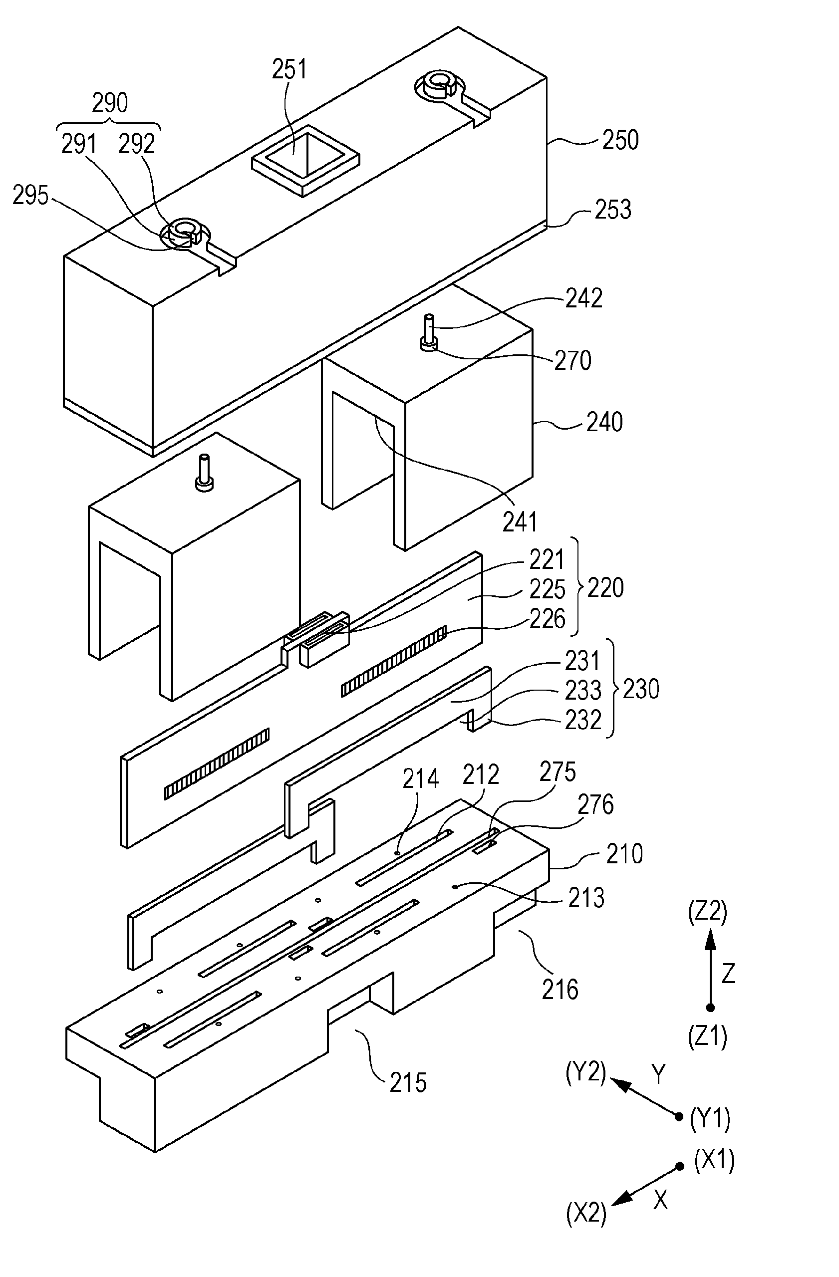
[0269]Here, a flow path member 240A according to another embodiment will be described. FIG. 21 is an exploded perspective view of the flow path member of a flow path member 240A, FIG. 22 is a cross-sectional diagram of FIG. 21, taken along line IIX-IIX in the second direction Y and the third direction Z, FIG. 23 is a cross-sectional diagram of FIG. 21, and taken along line IIXI-IIXI in the second direction Y and the third direction Z. Note that, the same constituent elements as in FIG. 16 to FIG. 19 are given the same reference numerals, and repeated description will be omitted.

[0270]As illustrated FIG. 21 to FIG. 23, in the flow path member240A, the feeding needle 242 is not disposed in the center portion in the first direction X, but is disposed at a position close to the X1 direction, and the branched flow path 3011 which communicates with the introduction path 301 inside the feeding needle 242 is provided immediately below the feeding needle 242. Accordingly, a flow path wall po...


PUM


Abstract

The invention is to provide a liquid ejecting head including a flow path member which allows a capacity of an air bubble chamber to be increased as much as possible and in which a filter is not clogged even when the variation of a liquid consumption amount is large, and a liquid ejecting apparatus including the flow path member. Alternatively, the invention is to provide a liquid ejecting head including a flow path member which allows a capacity of an air bubble chamber to be increased as much as possible while being miniaturized in a transporting direction and a liquid ejecting apparatus including the flow path member.

Description

CROSS-REFERENCE TO RELATED APPLICATIONS[0001]This application claims priority to Japanese Patent Application No. 2014-120021 filed on Jun. 10, 2014 and Japanese Patent Application No. 2014-120022 filed on Jun. 10, 2014. The entire disclosures of Japanese Patent Application Nos. 2014-120021 and 2014-120022 are hereby incorporated herein by reference.BACKGROUND[0002]1. Technical Field[0003]The present invention relates to a liquid ejecting head including a flow path member in which a flow path through which a liquid flows is formed and a liquid ejecting apparatus including the flow path member.[0004]2. Related Art[0005]A liquid ejecting apparatus which is represented by an ink jet type recording apparatus such as an ink jet type printer or plotter includes a liquid ejecting head that can eject a liquid such as ink stored in a cartridge, a tank, or the like. This liquid ejecting head includes a plurality of head main bodies which eject the liquid, and a flow path member that holds the ...

Claims


Application Information

Patent Timeline
IPC IPC(8): B41J2/175B41J2/19
CPCB41J2/19B41J2/17563B41J2/17513
Inventor NAWANO, MASAHISATAKINO, FUMIYA
Owner SEIKO EPSON CORP
Why Eureka
Try Eureka