Printing unit for printing plate elements from printing plates and converting machine comprising such a printing unit

a printing unit and printing plate technology, applied in printing presses, relief printing, printing, etc., can solve the problems of affecting the safety of operators, affecting the operation of printing units, so as to reduce the time taken and ensure the safety of operators

Active Publication Date: 2015-12-10
BOBST LYON
View PDF5 Cites 0 Cited by
  • Summary
  • Abstract
  • Description
  • Claims
  • Application Information

AI Technical Summary

Benefits of technology

This patent is about a printing machine that allows operators to change large printing plates easily. This reduces the number of operators needed to change plates and saves time. This is especially useful for converting machines that produce a lot of small runs. The machine has a transport system that makes it easy for a single operator to control. Overall, this invention makes it possible for a single operator to change printing plates, reducing the need for multiple operators and increasing efficiency.

Problems solved by technology

It is consequently difficult for an operator to handle these printing plates.
It thus takes a relatively long time to replace an earlier printing plate in the printing unit.
This replacement time forms a significant portion of the downtime of the converting machine.
Now a long downtime reduces the production volume and the profitability of the machine, in particular for converting machines producing a large number of small runs, where the printing plates are replaced frequently.
Conversely, bringing in two operators to replace a printing plate increases the production cost even more when these replacements are frequent.

Method used


Image

  • Printing unit for printing plate elements from printing plates and converting machine comprising such a printing unit
  • Printing unit for printing plate elements from printing plates and converting machine comprising such a printing unit
  • Printing unit for printing plate elements from printing plates and converting machine comprising such a printing unit

Examples


Embodiment Construction

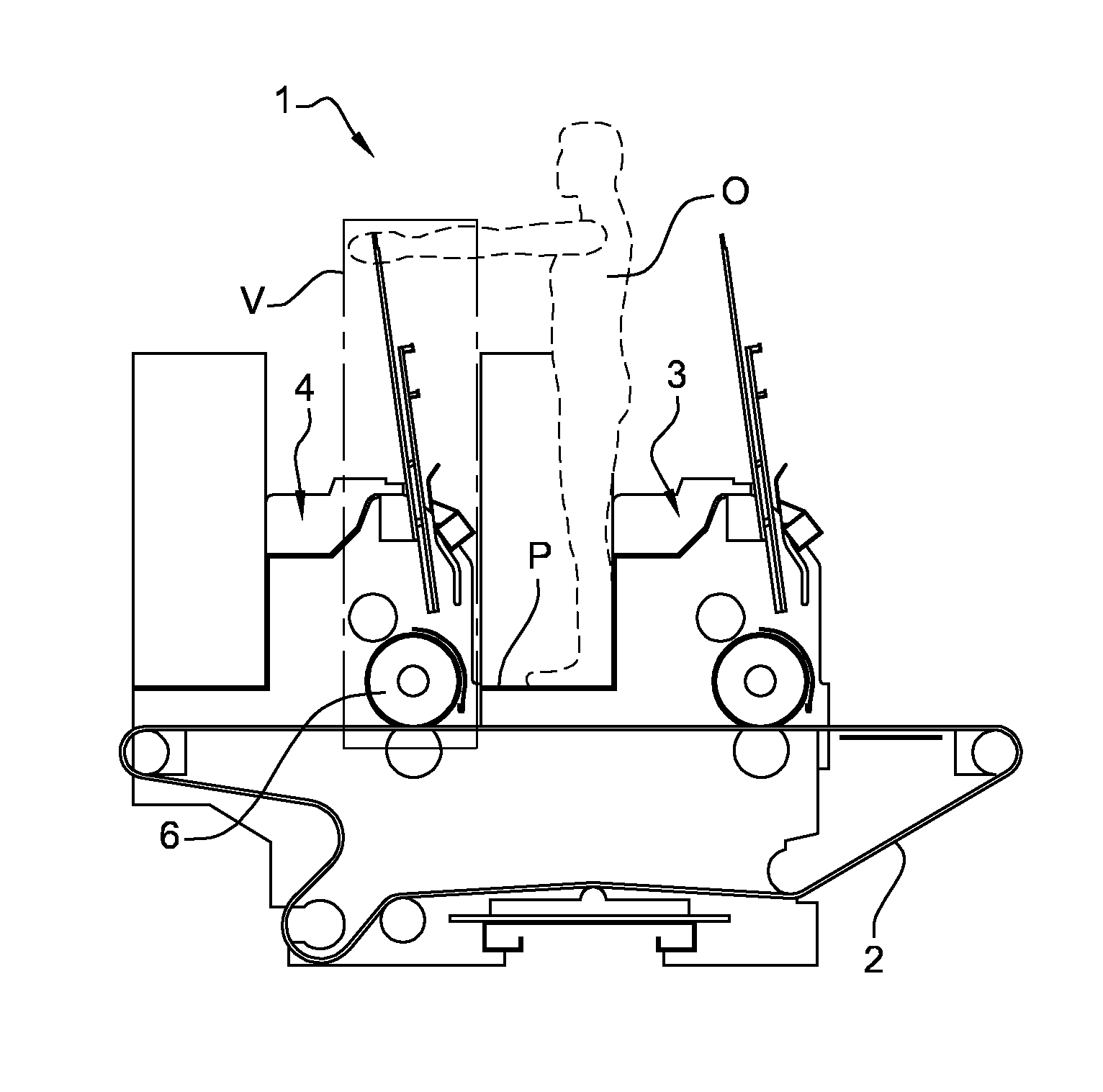
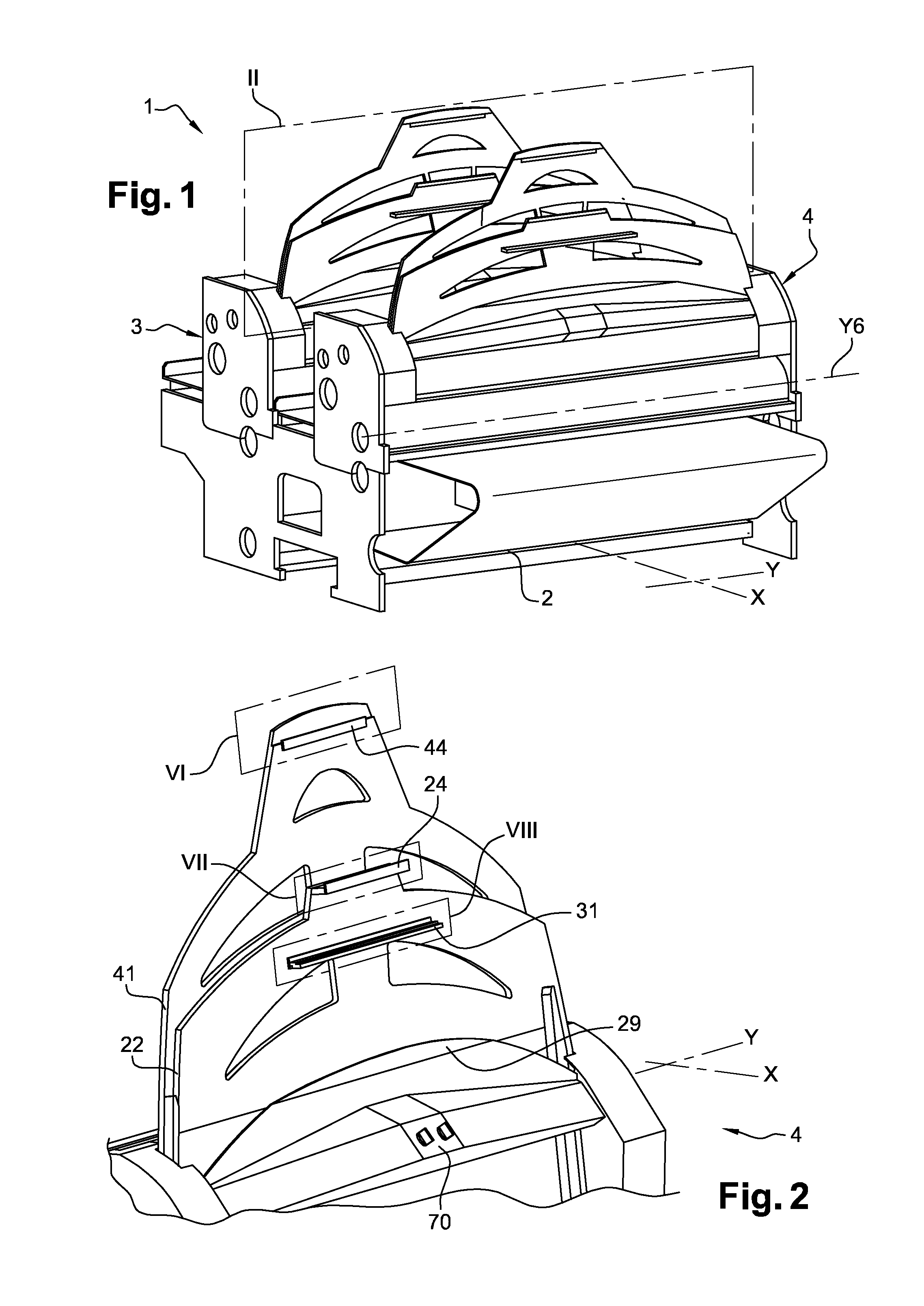
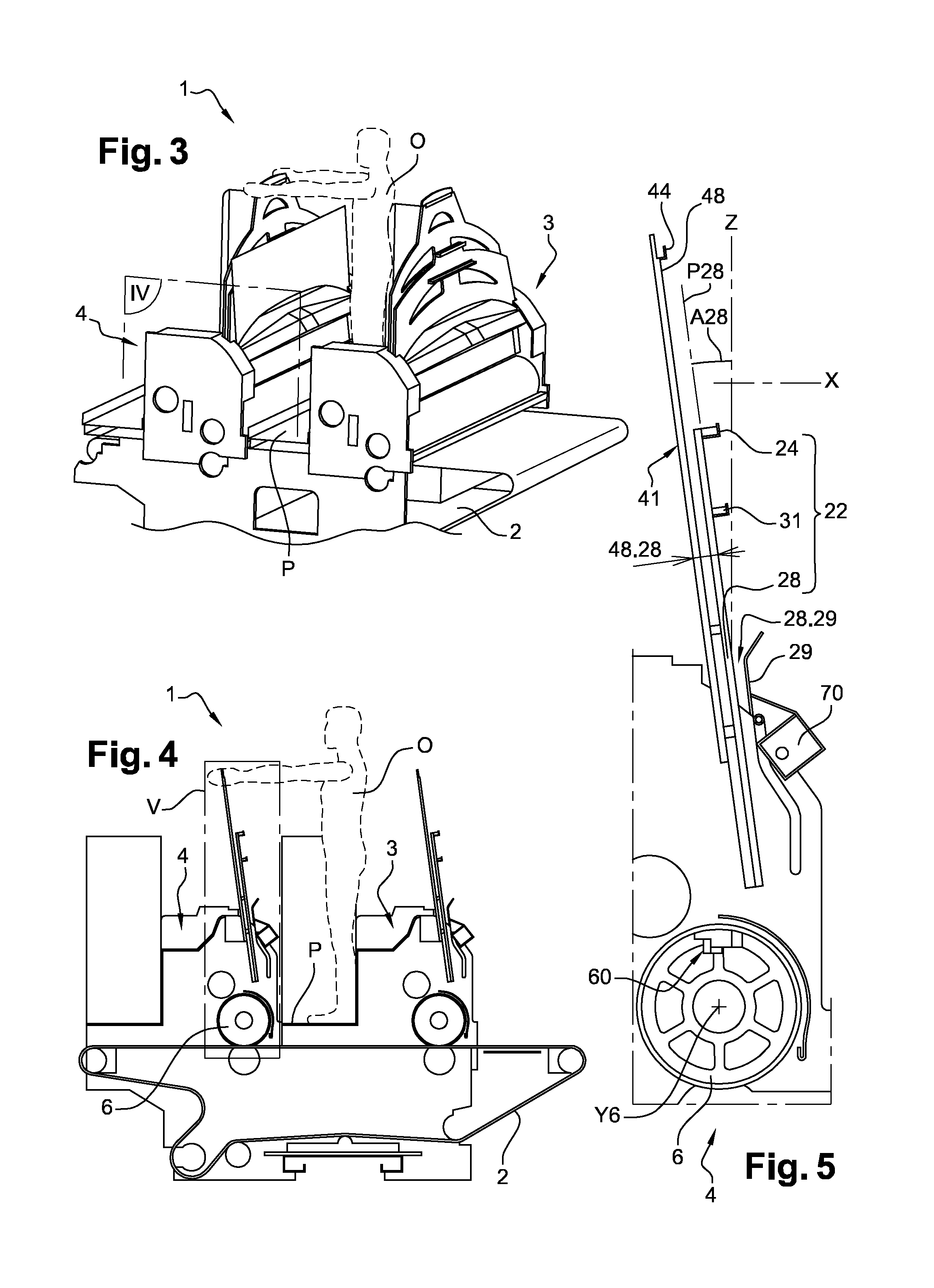
[0046]FIGS. 1 to 11 illustrate part of a converting machine 1 of the type for printing, folding and gluing, intended to process plate elements. In this case, the plate elements can be cardboard sheets.

[0047]The converting machine 1 comprises a transport system 2 and two printing units 3 and 4, which can be seen in FIGS. 1, 3 and 4. The printing units 3 and 4 are flexographic printing units. The printing units 3 and 4 are intended for making prints from flexible printing plates on cardboard sheets (not shown).

[0048]These cardboard sheets are conveyed by the transport system 2 in a so-called pushing direction or longitudinal direction X. In order to do this, the transport system 2 has a transport belt and members for driving the transport belt.

[0049]As the printing units 3 and 4 are similar, only the printing unit 4 is described below. The printing unit 4 has a plate cylinder 6 which is mounted so that it can rotate about a cylinder axis Y6. When the plate cylinder 6 is in service, th...


PUM


Abstract

A printing unit for making prints from printing plates on plate elements conveyed by a transport system having at least one plate cylinder mounted rotatably and suitable for carrying initially at least one earlier printing plate and then at least one later printing plate, the printing unit includes a primary support suitable for supporting the later printing plate, in a standby configuration, during printing using the earlier printing plate and during the unwinding of the earlier printing plate, and in an engaged configuration, during the winding of the later printing plate onto the plate cylinder, a portion of the later printing plate being attached to the plate cylinder, and a secondary support suitable for supporting the earlier printing plate unwound from the plate cylinder, in which the primary support includes a primary fastening member for fastening the later printing plate in the standby configuration, and a primary fastening mechanism for fastening the later printing plate in the engaged configuration.

Description

CROSS-REFERENCE TO RELATED APPLICATIONS[0001]The present application is a 35 U.S.C. §371 national phase conversion of PCT / EP2013 / 003865, filed Dec. 19, 2013, which claims priority of French Application No. 1262955, filed Dec. 28, 2012. The contents of both applications are incorporated by reference herein. The PCT International Application was published in the French language.FIELD OF INVENTION[0002]The present invention relates to a printing unit for making prints from printing plates on plate elements conveyed by a transport system ,and a converting machine comprising such a printing unit.FIELD OF APPLICATION[0003]The present invention can be applied to the field of processing plate elements, such as cardboard sheets, to form packaging boxes. The present invention can in particular be applied to converting machines, in particular machines combining printing, cutting, and folding / gluing.DEFINITIONS[0004]The term plate element refers to an overall flat product made of at least one m...

Claims


Application Information

Patent Timeline
Patent Type & Authority Applications(United States)
IPC IPC(8): B41F27/06
CPCB41F27/06B41F27/1206B41F27/1231B41P2200/12B41P2227/62B41P2227/63
Inventor GAVEGLIA, SERGEPERENET, REMY
Owner BOBST LYON
Why Eureka
Try Eureka