
Sensor system for corrosion monitoring

a technology of corrosion monitoring and sensor system, which is applied in the direction of analysing fluid using reradiation, and analysing solids using sonic/ultrasonic/infrasonic waves. it can solve the problems of inability to monitor the system permanently, the cui detection process is a slow manual process, and the inspection tool is expensiv

Active Publication Date: 2015-12-03
NORCE INNOVATION AS
View PDF3 Cites 7 Cited by
  • Summary
  • Abstract
  • Description
  • Claims
  • Application Information

AI Technical Summary

Benefits of technology

The invention is a new technology that uses acoustic emissions to monitor corrosion. This allows for the use of sound waves to probe corrosion while the fibre acts as a receptor for the sound. The technology also allows for continuous measurement over significant lengths without necessarily needing discrete humidity sensors. The invention can detect corrosion related parameters such as humidity, liquid water, pH, conductivity, salinity, and hydrogen. This means the technology can confirm the likelihood of corrosion, regardless of the level of humidity, and can measure humidity along the fibre with high resolution.

Problems solved by technology

Pipeline and process vessel corrosion under insulation is an enormous and costly problem across northern European oil and gas installations, and similar weather related challenges are likely to face other growing markets around the world such as those in Canada and Brazil.
At present CUI detection is a slow manual process requiring skilled inspectors with costly inspection tools.
There are no permanent monitoring systems available suitable for CUI purposes.
The problem is that such a measurement systems lacks a mechanism to confirm that corrosion has taken place.

Method used


Image

  • Sensor system for corrosion monitoring
  • Sensor system for corrosion monitoring

Examples


Embodiment Construction

[0026]Various aspects of the disclosure are described more fully hereinafter with reference to the accompanying drawings. This disclosure may, however, be embodied in many different forms and should not be construed as limited to any specific structure or function presented throughout this disclosure. Rather, these aspects are provided so that this disclosure will be thorough and complete, and will fully convey the scope of the disclosure to those skilled in the art. Based on the teachings herein one skilled in the art should appreciate that the scope of the disclosure is intended to cover any aspect of the disclosure disclosed herein, whether implemented independently of or combined with any other aspect of the disclosure. For example, an apparatus may be implemented or a method may be practiced using any number of the aspects set forth herein. In addition, the scope of the disclosure is intended to cover such an apparatus or method which is practiced using other structure, functio...


PUM

PropertyMeasurementUnit
corrosionaaaaaaaaaa
thicknessaaaaaaaaaa
lengthaaaaaaaaaa

Abstract

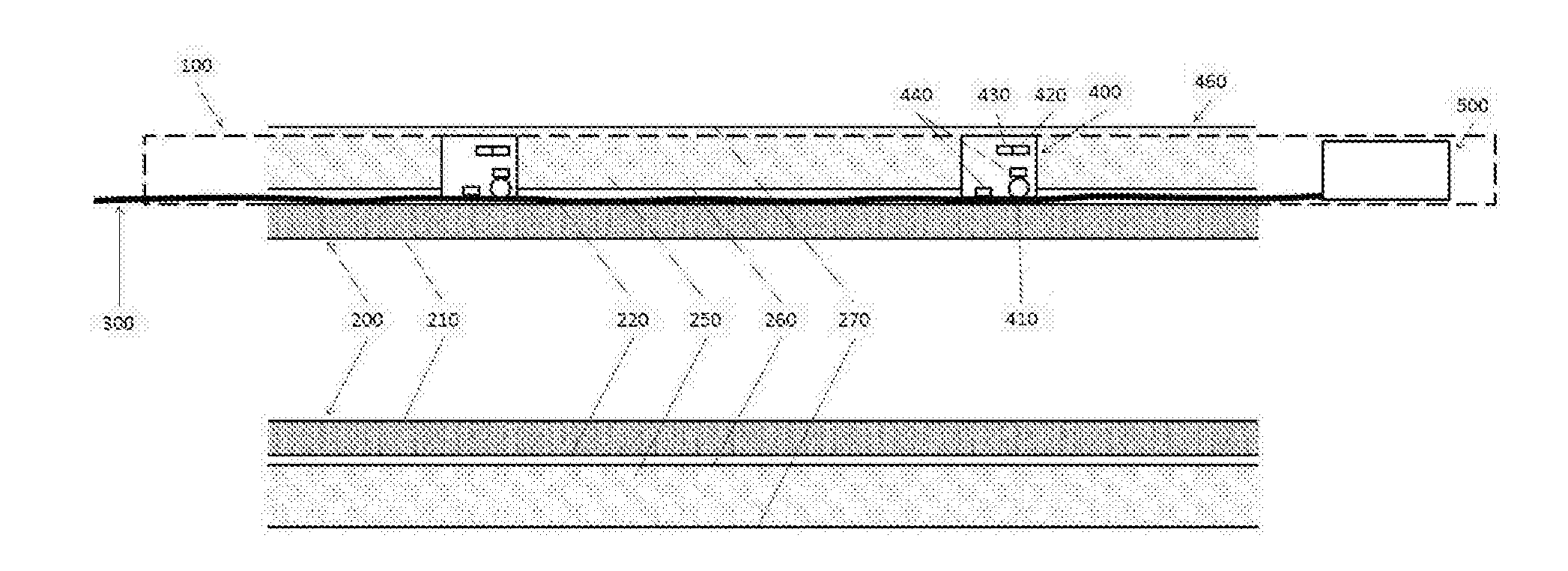
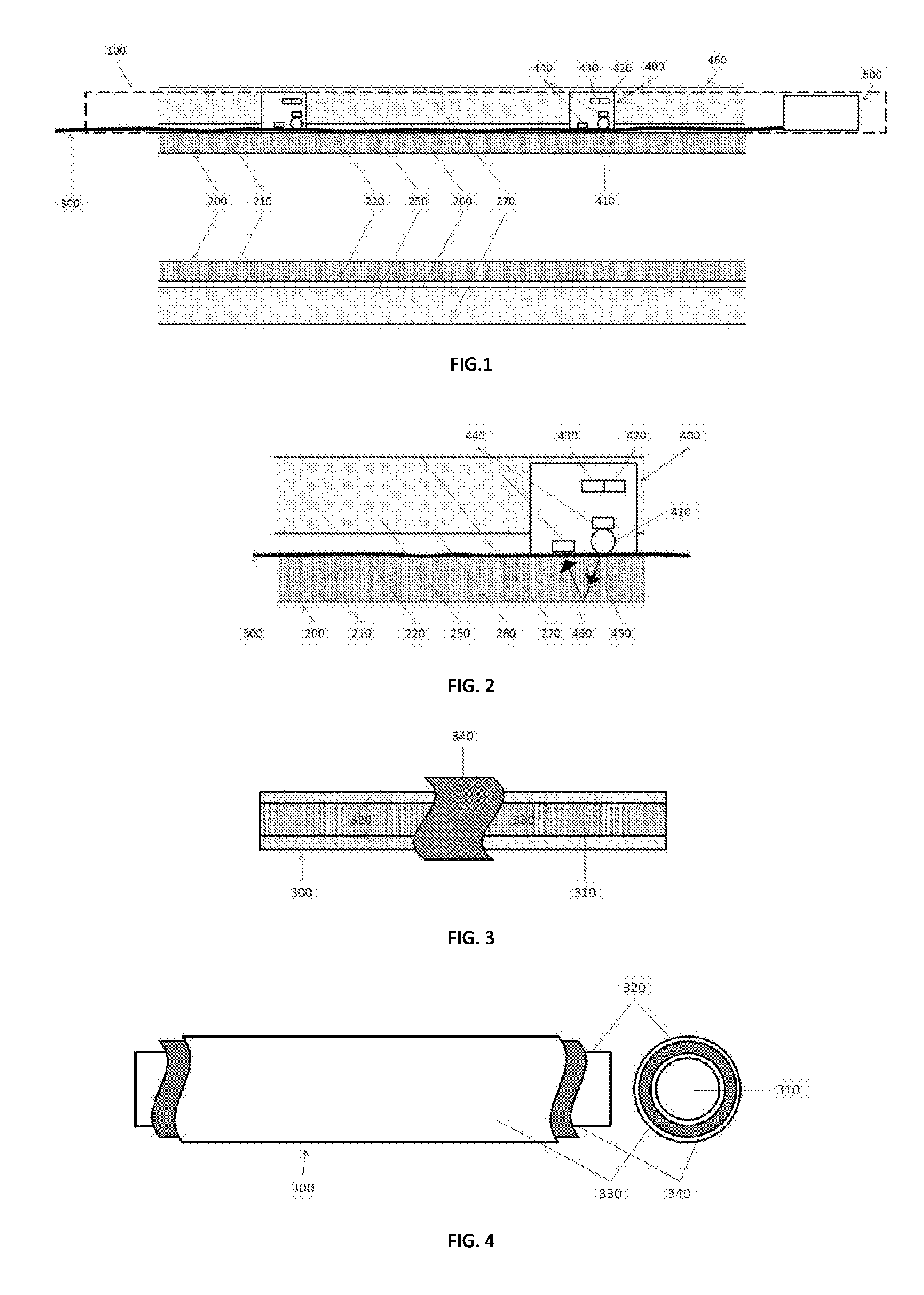
A permanently installed monitoring system for corrosion under insulation (PIMSCUI) and a method for performing the monitoring of said system are provided. The present invention attains the objective of the invention by a fibre optic cable permanently mounted between walls of a pipeline and pipeline insulation surrounding the pipeline and placement of acoustic emitters along the length of the pipeline in mechanical contact with the optical fibre. The acoustic emitters send a pulsed acoustic signal towards the pipeline which is received by the optical fibre, the acoustic signal subsequently travels through the pipeline wall, reflecting from the inner diameter of the pipeline before the reflected pulse is received at the optical fibre.

Description

BACKGROUND OF THE INVENTION[0001]1. Technical Field[0002]The invention relates to corrosion monitoring in general and more specifically a permanently installed monitoring system for corrosion under insulation (PIMSCUI) and a method for performing the monitoring of said system.[0003]2. Background Art[0004]Pipeline and process vessel corrosion under insulation is an enormous and costly problem across northern European oil and gas installations, and similar weather related challenges are likely to face other growing markets around the world such as those in Canada and Brazil. At present CUI detection is a slow manual process requiring skilled inspectors with costly inspection tools. There are no permanent monitoring systems available suitable for CUI purposes. Enormous direct cost reductions could be achieved through better decision making enabled by permanent monitoring technology. Savings would be magnified through the reduction of indirect costs such as CUI related shutdowns.[0005]F...

Claims


Application Information

Patent Timeline
Patent Type & Authority Applications(United States)
IPC IPC(8): G01N29/07G01N29/24G01N17/04
CPCG01N29/07G01N17/04G01N29/2475G01N2291/0423G01N2291/0421G01N2291/0422G01N2291/0427G01N17/046G01N29/2418G01N2291/0258G01N2291/02845G01N2291/02854
Inventor HUSEBO, MAGNEHELLEVANG, JON ODDVARTHOMAS, PETER JAMES
Owner NORCE INNOVATION AS
Learn More