
Bin system and method of regulating particulate flow from bins

a technology of bins and parts, applied in drying machines, lighting and heating apparatus, furniture, etc., can solve the problems of excessive drying of grains near the floor,

Inactive Publication Date: 2015-12-03
OGARY GREGORY HOWARD
View PDF5 Cites 17 Cited by
  • Summary
  • Abstract
  • Description
  • Claims
  • Application Information

AI Technical Summary

Benefits of technology

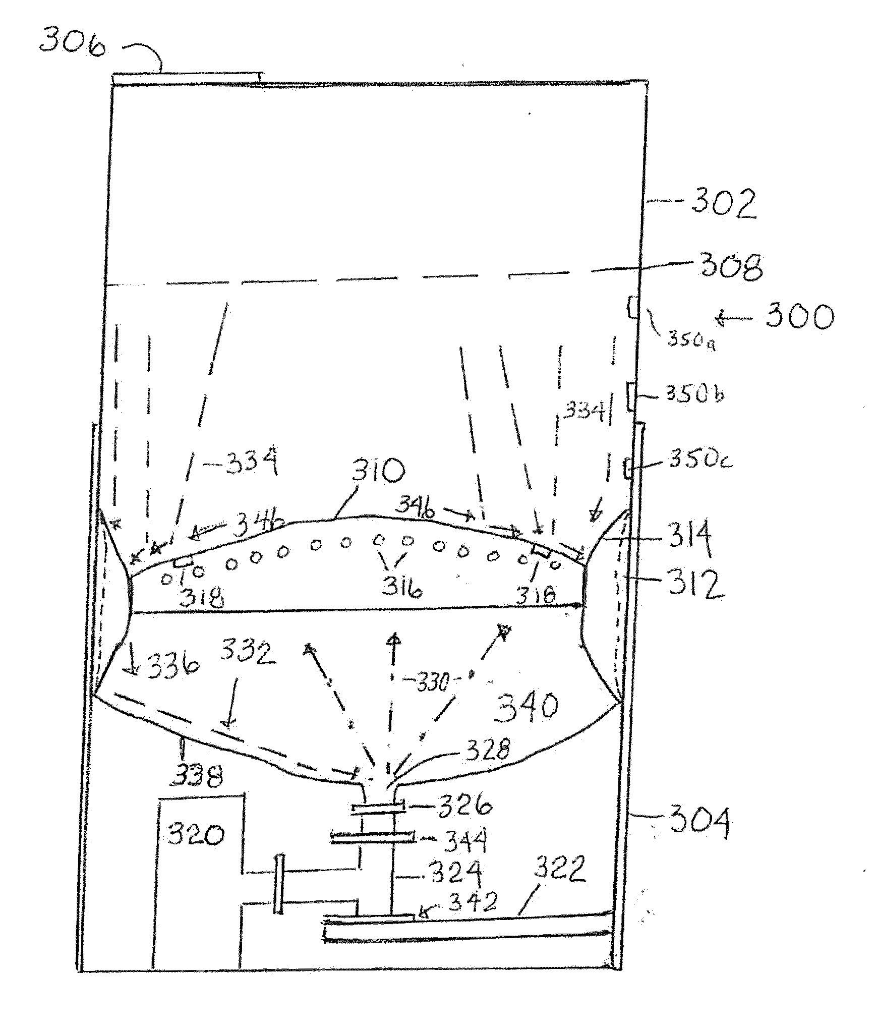
The patent describes a bin for containing and delivering particles. The bin has a housing with a support plate for holding the particles. The support plate has a porous structure for air flow. The top of the housing has an air flow area between it and the support plate. The sides of the support plate have a particle drop region around them. A sealing and opening component is within this region, which can seal or open a path for the particles to pass through. This component can expand to seal the particle drop region, or retract to open it for particle passage. This design allows for controlled delivery of particles without exposing them to air, which can cause damage or contamination.

Problems solved by technology

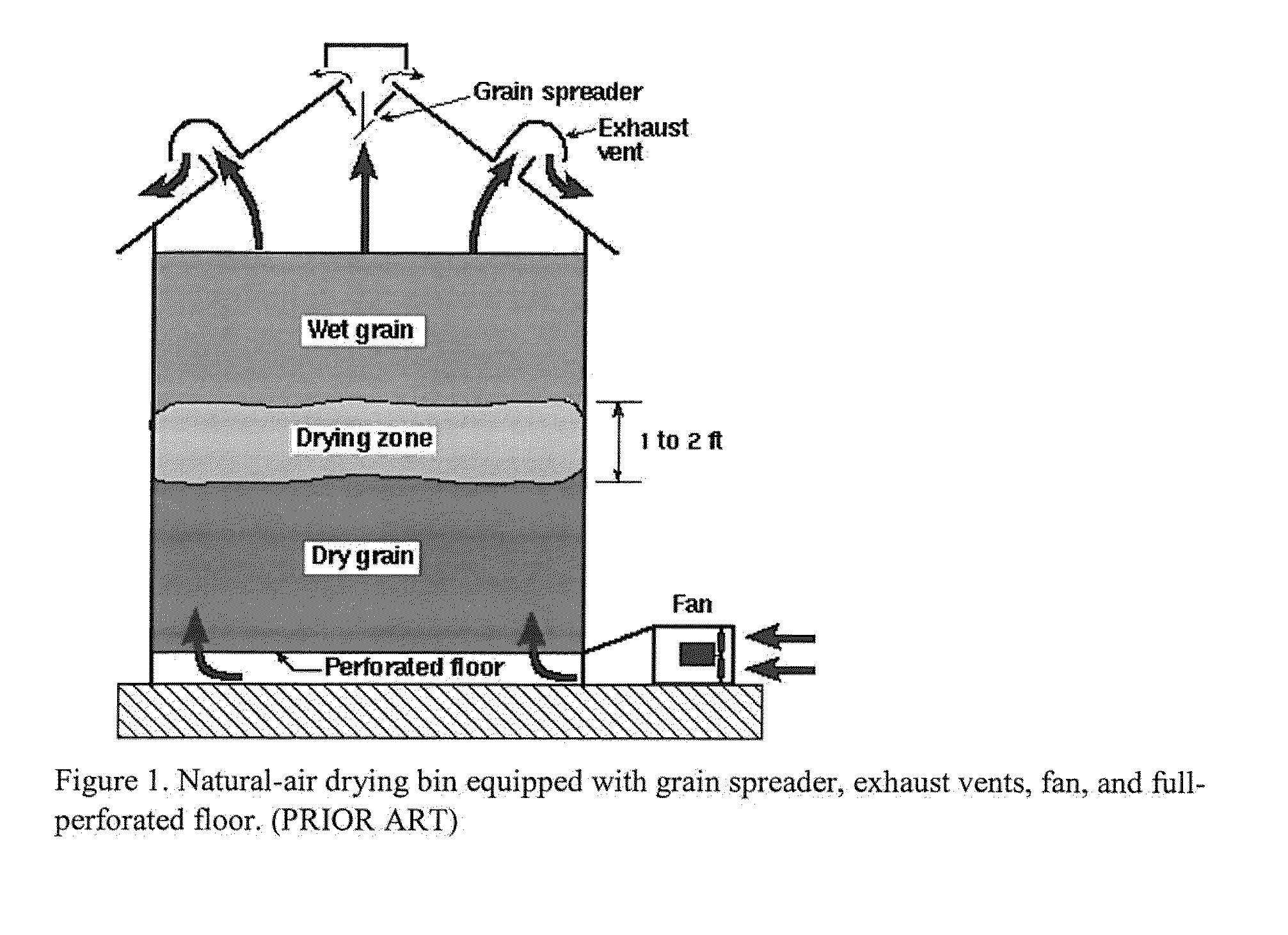
However, grain near the floor often becomes excessively dried while the top layer of grain often stays moist.

Method used


Image

  • Bin system and method of regulating particulate flow from bins
  • Bin system and method of regulating particulate flow from bins
  • Bin system and method of regulating particulate flow from bins

Examples


Embodiment Construction

[0033]The present technology includes a bin (or any other solid storage container) for containment and delivery of particulate materials. The bin may store, and possibly treat the particulate materials within the bin. The bins are designed for particulates having a number average diameter size. The individual bins may be modified to contain specific ranges of particle materials, as will be discussed herein. The bin may have:[0034]a) a housing comprising a top, a bottom and side walls;

[0035]The housing is made of structural materials sufficient to operate under the stress of use. This stress includes all of physical stress, strain, weight, chemical contact, organic contact and vibration as well as ambient conditions (including weather if used outdoors). Typical structural materials would include metals (such as carbon steel, high strength low alloy steel, stainless steel and aluminum), polymeric materials, ceramics, wood (primarily for framing) and composites.[0036]b) s particulate m...


PUM


Abstract

A bin and method of use for containment and delivery of particulate materials has:a) a housing;b) a particulate materials support plate within the housing, the support plate having a porous structure allowing air flow therethrough;c) the support plate having a central area elevated away from the bottom of the housing and surrounding sides;d) an air flow area between the bottom of the housing and the support plate;e) a particle drop region surrounding the sides of the support plate; andf) a sealing and opening component within the particle drop region that seals and opens a particle drop path between the support plate and the side walls of the housing.The sealing and opening component has an expanded position when sealing the particle drop region and is in a retracted position when opening the particle drop region to particulate material passage.

Description

BACKGROUND OF THE INVENTION[0001]1. Field of the Invention[0002]The present invention relates to the field of storage or processing bins for particulate materials and for processes for removing the particulate materials from the bins. Bin structures, methods of use of the bins and methods of removing particulate materials from the bins are enabled.[0003]2. Background of the Art[0004]Bins are used in a wide range of technologies to store, treat, deliver and dry particulate materials. Typically bins are used with particles having average sizes of at least one millimeter (1 mm), and preferably with more moderate size particles of from 1-100 millimeters, and more particularly from number average particle size diameters of from 20-50 millimeters and more particularly from 4-40 millimeters.[0005]Bins are used in mining industries, waste storage and disposal technologies, recycling industries, pharmaceutical technologies, particle drying technologies, plastic molding industries, agricultur...

Claims


Application Information

Patent Timeline
IPC IPC(8): F26B9/06F26B5/00
CPCF26B5/00F26B9/063F26B25/001F26B25/10
Inventor O'GARY, GREGORY HOWARD
Owner OGARY GREGORY HOWARD
Learn More