
Applications of ultra-low viscosity fluids to stimulate ultra-tight hydrocarbon-bearing formations

Inactive Publication Date: 2015-12-03
STATOIL GULF SERVICES
View PDF14 Cites 17 Cited by
  • Summary
  • Abstract
  • Description
  • Claims
  • Application Information

AI Technical Summary

Benefits of technology

The present invention provides a method for recovering hydrocarbons from a subterranean formation with low matrix permeability using a two-step process. The first step involves injecting a low-viscosity fluid, such as carbon dioxide, into the formation through a well. The second step involves injecting a second fluid, such as a gelled aqueous fluid or foam, into the formation before, after, or both before and after injecting the first fluid. The second fluid may carry proppant. The method may also involve flushing the formation with the first fluid before producing the hydrocarbons. The invention also includes a hydrocarbon recovery system comprising an injection apparatus, storage containers, and a valve for injecting the first fluid into the formation. The technical effects of the invention include improved oil and gas recovery from low-permeability formations and simplified well construction.

Problems solved by technology

Horizontal drilling results in increased reservoir contact with the production well.
Often, high injection rates are required to fracture a subterranean formation effectively.
These high rates result in substantial pressure drops through the well due to friction.
Another challenge with hydraulic fracturing is effectively transporting and placing proppant.
It is largely accepted that low viscosity fluids create more complex fracture networks with more effective connectivity to the formation, but these fluids cannot effectively transport or place proppant deep in the formation.
After the fracturing operation, fractures appear in the formation.
Furthermore, during the change from (gel-like) liquid to gas form, the LPG volume increases greatly, thereby increasing the pressure in the formation and further extending fractures.
Compared to many other methods of hydraulic fracturing, the method based on LPG does not leave chemical substances in the soil and also reduces the effect of reflux.
This operation creates issues with handling the added chemicals and also with handling large amounts of water (when the fracturing fluid is water-based).
The cost of proppant may be up to 10% of the drilling costs.
Extracting hydrocarbons from shale reservoirs can be difficult because the shale formation is of low porosity and low permeability, so fluid hydrocarbons may not be able to find a path through the formation towards a production well.
As such, when a well is drilled into the formation, only those fluid hydrocarbons in proximity to the well are produced, as the other hydrocarbons farther away from the well have no easy path to the well through the relatively impermeable rock formation.
The use of resin coated proppants is incompatible with the temperatures required for kerogen pyrolysis.
Furthermore, flow of hard proppants may cause erosion to pipes, production equipment and to the rock itself.
Oil production rates from such reservoirs under primary depletion often dramatically decline, resulting in oil rates that are only a small fraction of the initial production rates in a relatively short time.
Oil recovery is further impeded by large water cuts (that is, the ratio of water produced in comparison to the total volume of liquids produced) during primary depletion, which can range upwards of 80% in some cases.
The disadvantages of these gelled fluid systems include high pipe friction if gelling is not delayed, excessive formation damage if the breaking of macromolecules is not adequate, a limited rate and pressure can be applied to the formation, and only a limited stimulated reservoir area is covered compared to slickwater systems.
In addition, complicated chemistry designs are required.
In addition to the disadvantages of gelled fluids discussed above, the foams and emulsions can be expensive and usually have a high friction pressure compared to other gelled fluids and slickwater.
The disadvantages of slickwater include poor proppant suspension and transport compared to gelled fluids, limited fracture conductivity generation, and formation damage due to deposition of macromolecules.
The disadvantages of the hybrid gel systems include the same inherent formation and fracture conductivity disadvantages as with gelled fluid and slickwater.
However, the hybrid gel system will have limited proppant suspension and transport with the slickwater portion of the treatment and will have limited producible stimulated reservoir area with the gelled fluid portion of the treatment.
These fluids are applied to reservoirs where water-sensitivity adversely impacts production and where aqueous fluids may cause significant (and sometimes irreversible) formation damage (e.g., coal bed methane formations or any formations with appreciable swelling clays).
However, pure CO2 and N2 cannot carry proppant effectively and near well bore conductivity could be compromised.
In addition, non-aqueous fluids (particularly nitrogen and carbon dioxide) may be applied to a limited subset of reservoir types due to costs, relatively high matrix leakoff, and relatively poor proppant transport.
Though oil recovery from unconventional reservoirs is economical today, a number of challenges (e.g., fast decline rates and low ultimate recoveries) restricting the full potential of these reservoirs still exist.
While the hybrid stimulation methods used today with aqueous systems (in comparison to crosslinked fluid systems typically used in conventional reservoirs) did help increase fracture surface area and partially overcome deficiencies related to the low matrix permeability, access to the bulk of the reservoir (i.e., producible stimulated reservoir area) is still very limited using these methods for two primary reasons.
The first reason is the lack of stimulated area per volume of reservoir (i.e, limited number of stimulated fractures per volume of reservoir), and the second reason is restricted flow paths in un-propped, fractured reservoirs due to water damage.
Water-based fluids may also damage narrow fractured pathways due to clay swelling and fines migration, interfacial tension with reservoir hydrocarbons, and gelling agents used in the stimulation fluids.

Method used


Image

  • Applications of ultra-low viscosity fluids to stimulate ultra-tight hydrocarbon-bearing formations
  • Applications of ultra-low viscosity fluids to stimulate ultra-tight hydrocarbon-bearing formations
  • Applications of ultra-low viscosity fluids to stimulate ultra-tight hydrocarbon-bearing formations

Examples


Embodiment Construction

[0039]The present invention will now be described with reference to the accompanying drawings.

[0040]The present invention is directed to methods of recovering hydrocarbons from a hydrocarbon-bearing formation with a matrix permeability of less than 1 mD.

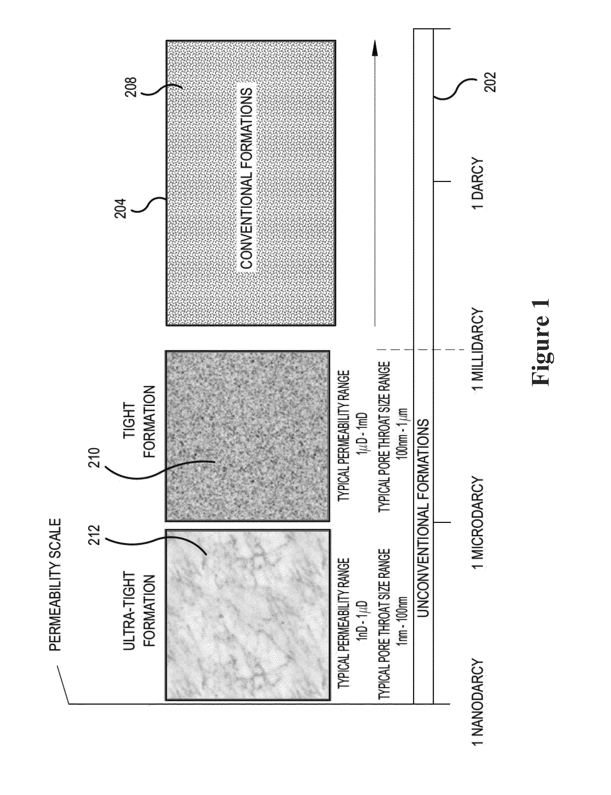
[0041]In this regard, a manner of identifying the potential success of oil recovery from subterranean formations is to characterize the permeability characteristics of the formation. Permeability is a measurement of the resistance to fluid flow of a particular fluid through the reservoir and is dependent on the structure, connectivity, and material properties of the pores in a subterranean formation. Permeability can differ in different directions and in different regions.

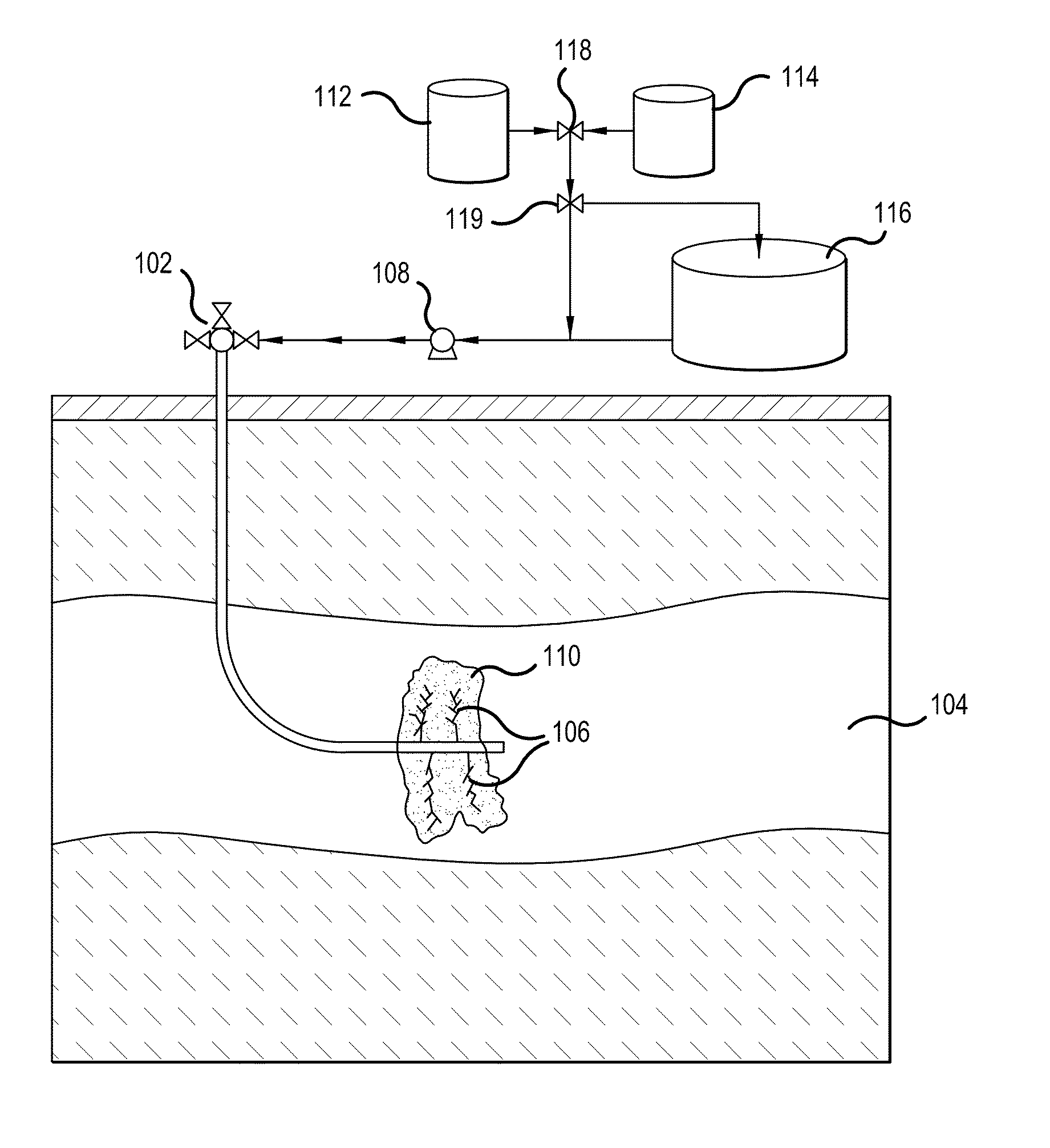
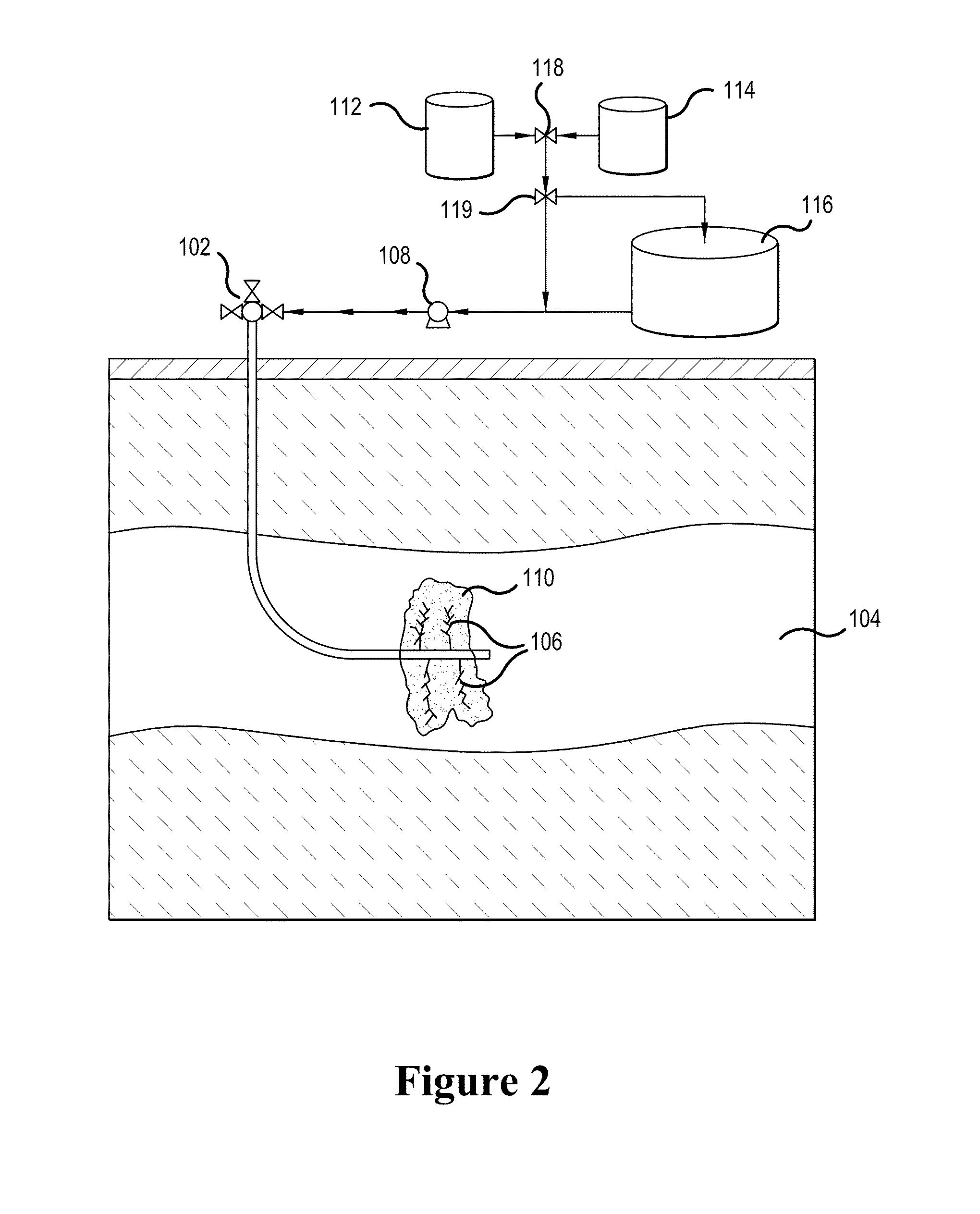
[0042]FIG. 1 is an example of a tight to ultra-tight hydrocarbon-bearing subterranean formation 104 as depicted in FIG. 2. A tight to ultra-tight formation is characterized in terms of permeability or permeability scale 202. In a conventional formation 204, the pore...


PUM


Abstract

A method of recovering hydrocarbons from a hydrocarbon-bearing subterranean formation with a matrix permeability of less than 1 mD is disclosed. The method includes injecting a volume of a first fluid having a viscosity lower than the viscosity of water into an injection well present in the formation; separately injecting a volume of a second fluid into the formation before, after, or before and after injecting the first fluid; and producing at least a fraction of the injected volume of the first fluid and hydrocarbons from the formation through a production well present in the formation.

Description

BACKGROUND OF THE INVENTION[0001]1. Field of the Invention[0002]The present invention relates to applications of ultra-low viscosity fluids to stimulate ultra-tight hydrocarbon-bearing formations.[0003]2. Description of Background Art[0004]Over the years, enormous strides in various oil extraction and oil recovery (also referred to as “oil production”) methods have been achieved, ranging from improved oil recovery (“IOR”) methods, incorporating technologies such as water injection into subterranean oil-bearing formations, to enhanced oil recovery (“EOR”) methods, incorporating technologies such as gas injection into subterranean oil-bearing formations.[0005]Mature EOR technologies include gas-injection-based methods, microbial-based methods, chemical-based methods, and thermal-based methods. Thermal methods and gas injection are the two most commonly applied EOR technologies commercially. Thermal methods include technologies such as Steam Assisted Gravity Drainage (SAGD) and Cyclic ...

Claims


Application Information

Patent Timeline
IPC IPC(8): E21B43/16C09K8/594C09K8/80C09K8/70
CPCE21B43/164C09K8/70C09K8/805C09K8/80C09K8/594C09K8/58C09K8/60C09K8/62E21B43/166E21B43/255E21B43/267Y02P90/70
Inventor BRYANT, JASONIVARRUD, ENDRERIBEIRO, LIONELLI, HUINA
Owner STATOIL GULF SERVICES
Learn More