
Electromagnetic energy output system

a technology of electromagnetic energy and output system, which is applied in the field of lasers, can solve the problems of large pulse duration and pulse interval of laser output optical energy waveform, and is not adequately or optimally suited for a number of soft tissue cutting procedures

Inactive Publication Date: 2015-12-03
BIOLASE INC
View PDF3 Cites 6 Cited by
  • Summary
  • Abstract
  • Description
  • Claims
  • Application Information

AI Technical Summary

Benefits of technology

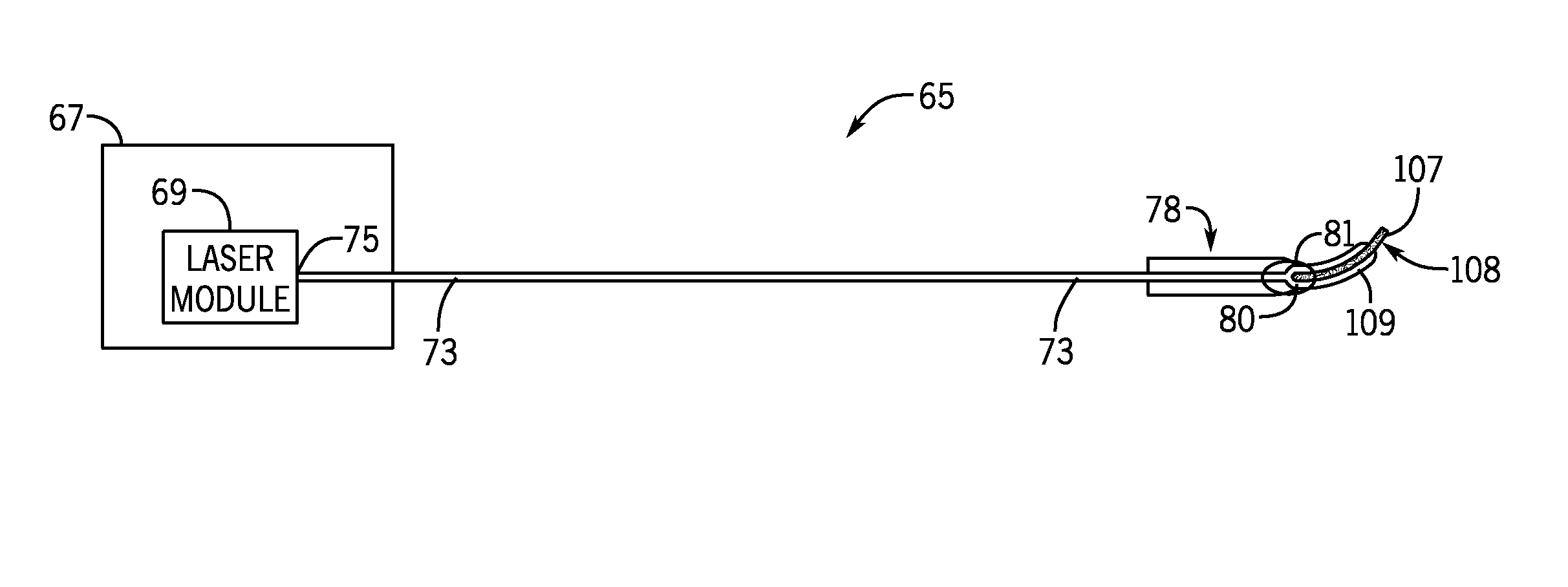
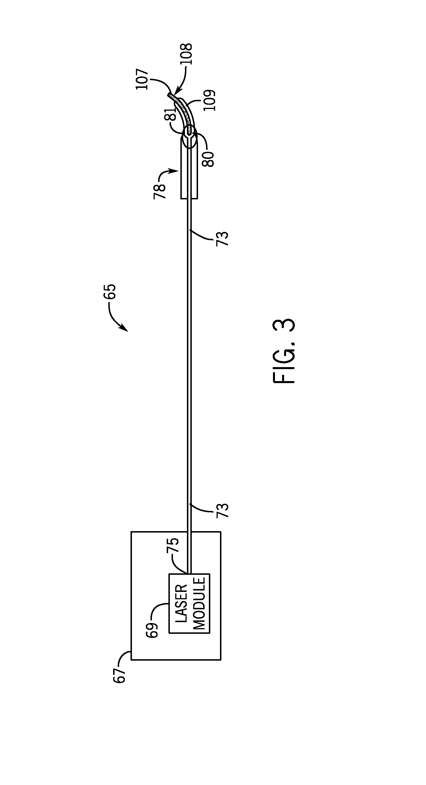
The present invention is an apparatus that includes a laser diode and a handpiece with a bendable tip cannula. This invention has various technical effects that can be utilized in various applications such as medical procedures. The technical effects of this invention include increased precision, improved accuracy, and reduced risk of complications during medical procedures. The invention can be used in different ways and with different tools to achieve better results in a safe manner.

Problems solved by technology

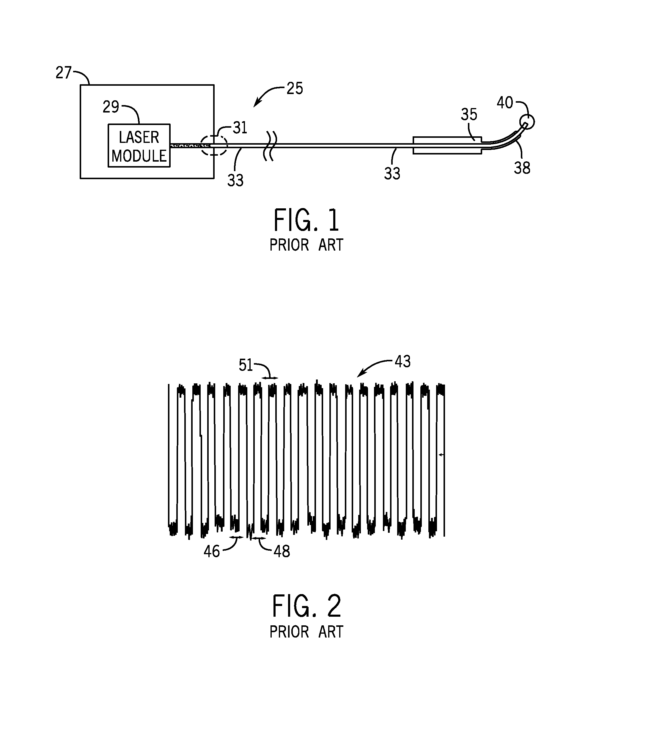
Additionally, while being independently adjustable, the pulse duration and pulse interval of the laser's output optical energy waveform tend to be relatively large and not adequately or optimally suited for a number of soft tissue cutting procedures, such as procedures designed to minimize an impartation of thermal energy into the target soft tissue.

Method used


Image

  • Electromagnetic energy output system
  • Electromagnetic energy output system
  • Electromagnetic energy output system

Examples


Embodiment Construction

[0035]Reference will now be made in detail to particular embodiments of the invention, examples of which are illustrated in the accompanying drawings. Wherever possible, the same or similar reference numbers are used in the drawings and the description to refer to the same or like parts. It should be noted that the drawings are in simplified form and are not to precise scale. In reference to the disclosure herein, for purposes of convenience and clarity only, directional terms, such as, top, bottom, left, right, up, down, over, above, below, beneath, rear, and front, are used with respect to the accompanying drawings. Such directional terms should not be construed to limit the scope of the invention in any manner.

[0036]Although the disclosure herein refers to certain illustrated embodiments, it is to be understood that these embodiments are presented by way of example and not by way of limitation. The intent of this disclosure, while discussing exemplary embodiments, is that the fol...


PUM


Abstract

An apparatus having an excitation source that includes at least one laser diode and also having a handpiece with a disposable, bendable tip cannula is disclosed. The bendable tip can include a pliable material possessing a treatment characteristic of being bendable by a user three or more times without kinking from a generally straight orientation to a self-supporting bent configuration spanning an angle of at least forty degrees while remaining fully operational.

Description

RELATED APPLICATIONS[0001]This application is a continuation of U.S. patent application Ser. No. 11 / 698,345, filed Jan. 25, 2007, the entire contents of which are incorporated herein by reference.BACKGROUND OF THE INVENTION[0002]1. Field of the Invention[0003]The present invention relates generally to devices for generating output optical energy distributions and, more particularly, to lasers.[0004]2. Description of Related Art[0005]A variety of laser systems have existed in the prior art. A solid-state laser system generally comprises a laser rod for emitting coherent light and a stimulation source for stimulating the laser rod to emit the coherent light. Flashlamps are typically used as stimulation sources for laser systems, for example, but diodes may be used as well for the excitation source. The use of diodes for generating light amplification by stimulated emission is discussed in the book Solid-State Laser Engineering, Fourth Extensively Revised and Updated Edition, by Walter...

Claims


Application Information

Patent Timeline
Patent Type & Authority Applications(United States)
IPC IPC(8): A61B18/22H01S5/062H01S5/00
CPCA61B18/22A61B2017/00477H01S5/06216H01S5/005A61B18/20A61B2018/2238
Inventor BOUTOUSSOV, DMITRIJONES, JEFFREY W.CELY, JULIO GUILLERMOANDRIASYAN, MANVEL ARTYOM
Owner BIOLASE INC
Learn More