
Knee brace

a knee brace and knee technology, applied in the field of knee brace, can solve the problems of extreme discomfort and the effect of bending, and achieve the effect of easy to achiev

Active Publication Date: 2015-11-26
MEDI GMBH & CO KG
View PDF6 Cites 8 Cited by
  • Summary
  • Abstract
  • Description
  • Claims
  • Application Information

AI Technical Summary

Benefits of technology

The invention is a knee brace with two separate tension straps that adjust the pressure on the pressure pad. The first straps extend directly over the pressure pad and can be tightened to exert a higher or lower pressure. The second straps, which are offset in the height direction from the first, prevent the patella from being pushed upward and enhance comfort. A second pressure pad is also included to prevent the patellar tendon from being stretched uncomfortably. A pocket is attached to the brace for added comfort. The technical effect is an improved knee brace that provides optimal pressure and stability while being comfortable to wear.

Problems solved by technology

Therefore, it has no effect on the bending of the knee, nor does it exert any pressure on the area of the hollow of the knee, which would be perceived as extremely uncomfortable.

Method used


Image

  • Knee brace
  • Knee brace
  • Knee brace

Examples


Embodiment Construction

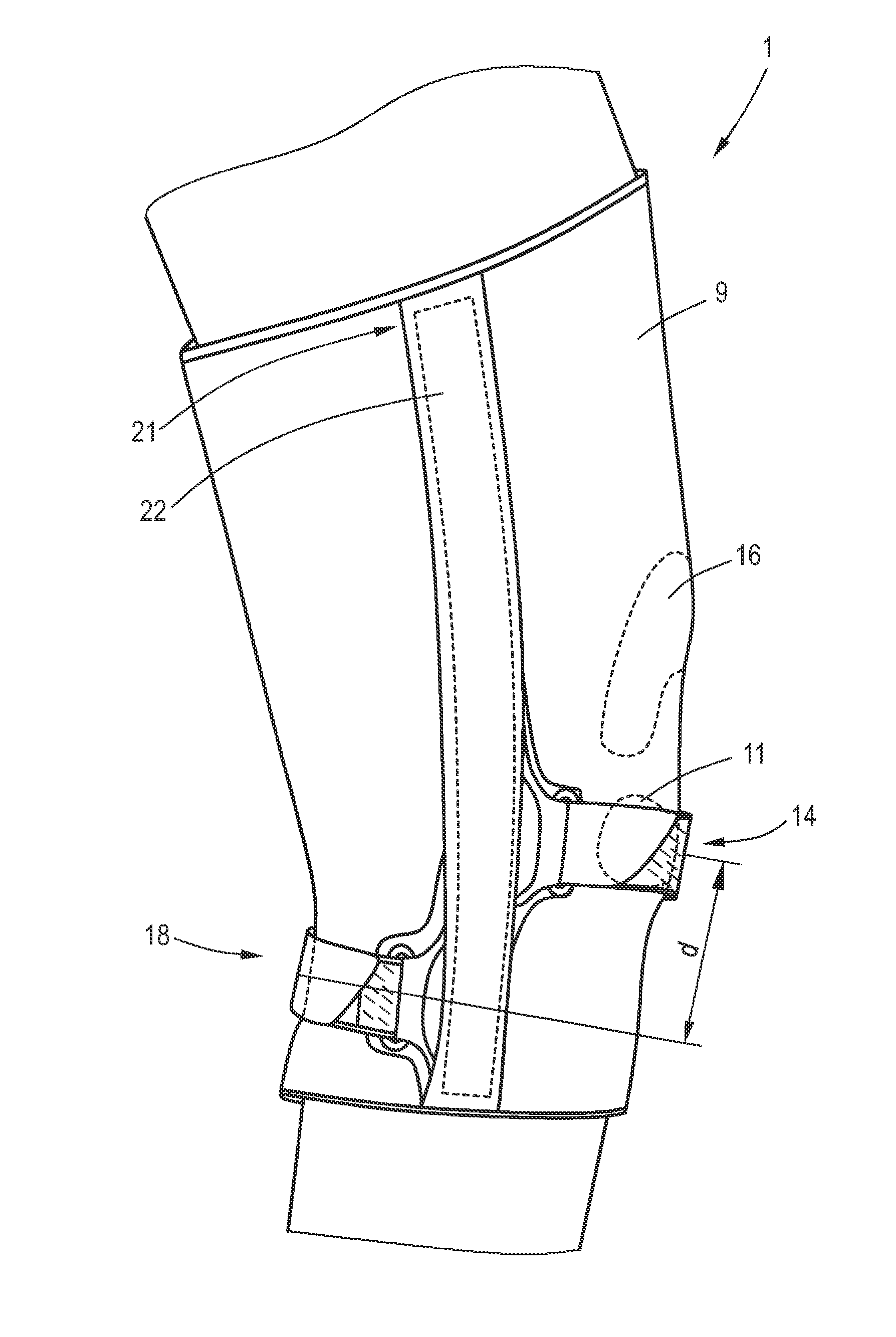
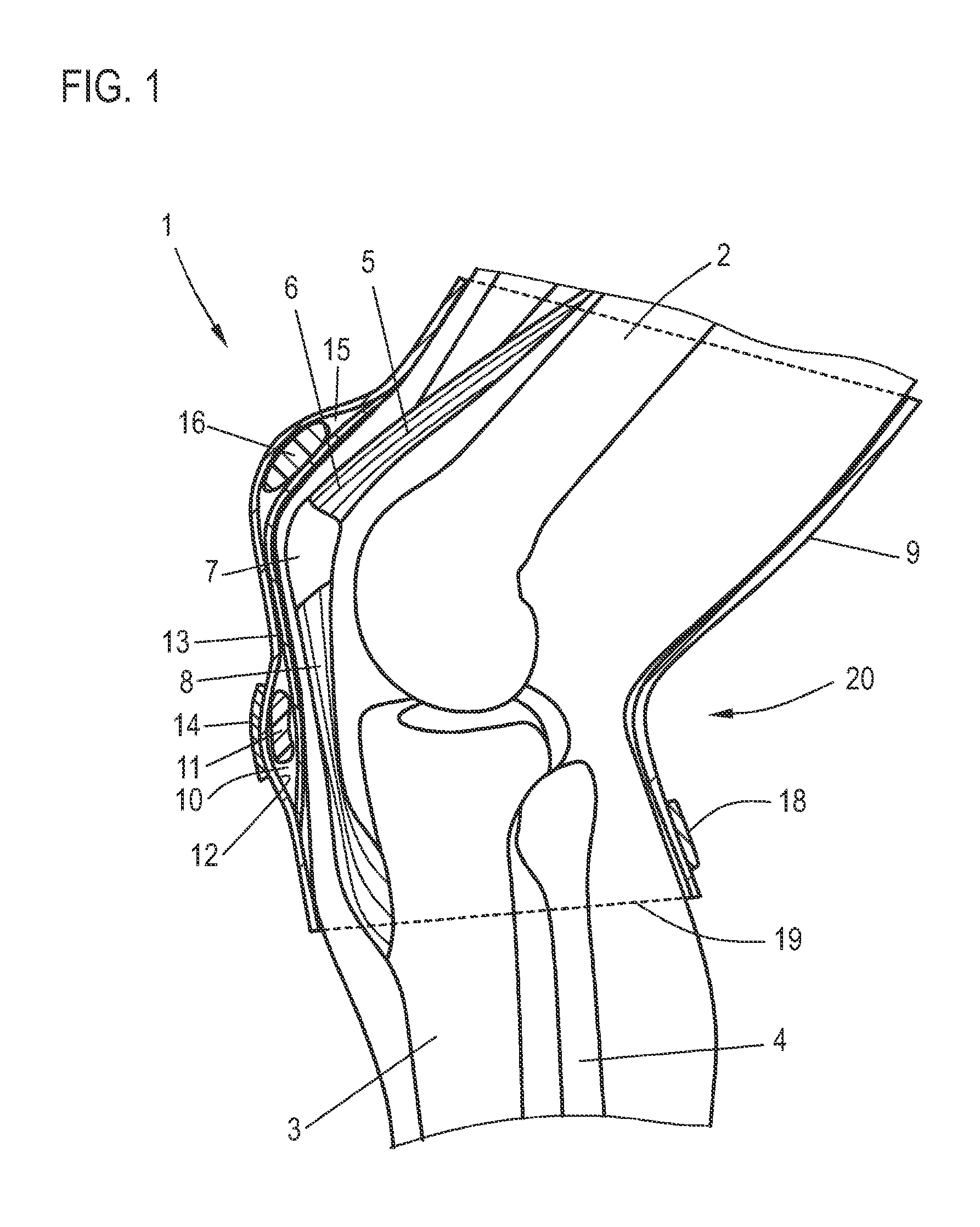
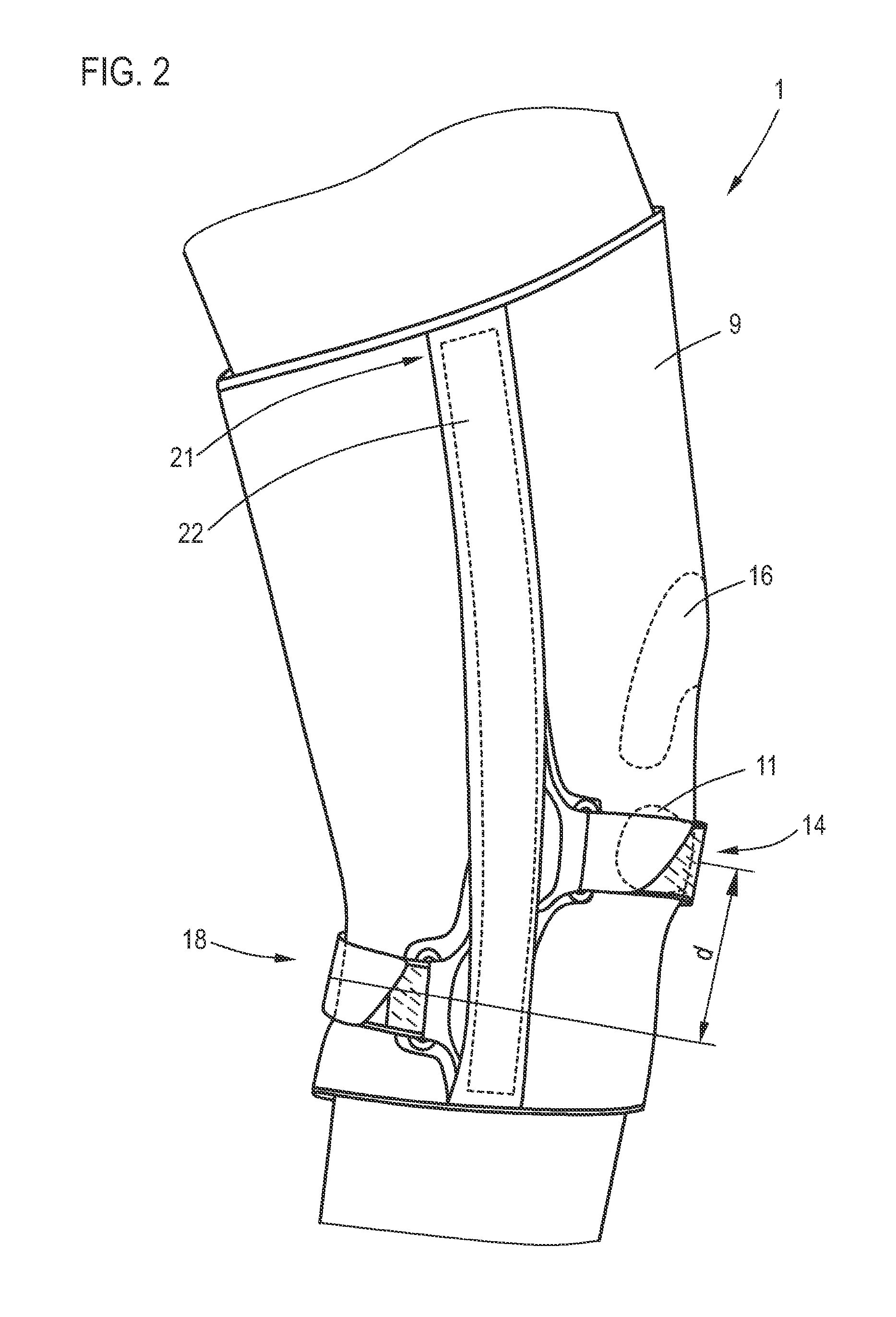
[0026]FIG. 1 shows a schematic diagram of the human knee, on which a knee brace 1 according to the invention is arranged. Shown are the femur 2, the tibia 3, and the fibula 4. The quadriceps muscle 5 is connected by a tendon 6 to the patella 7, which for its own part is connected by the patellar tendon 8 to the tibia 3. Extending around the knee is the knee brace according to the invention. This knee brace consists of a tubular elastic knitted body 9, on the front side of which a first pocket 10 is formed, in which a pressure pad 11 is arranged, which, when the brace is being worn as in FIG. 1, extends transversely across the patellar tendon 8. The pocket 10 is formed by a flat section 13, consisting, for example, of a knitted or woven piece of fabric, e.g., terrycloth, attached to the inside surface 12 of the knitting. This flat section 13 can be attached by means of an adhesive, for example. Above the pressure pad 11, a tension strap 14 extends across the outside surface of the kn...


PUM


Abstract

A knee brace having a tubular elastic knitted body with at least one pressure pad arranged thereon, which, when the brace is being worn, extends across the patellar tendon. On the front side of the knitted body, a first tension strap is provided, which extends around only a certain part of the knitted body and passes over the pressure pad. On the rear side of the knitted body, a second tension strap is provided, which is offset in the height direction from the first tension strap, and which extends around only a certain part of the knitted body.

Description

CROSS-REFERENCE TO RELATED APPLICATIONS[0001]The present application claims priority of DE 10 2014 107 239.1, filed May 22, 2014, the priority of this application is hereby claimed and this application is incorporated herein by reference.BACKGROUND OF THE INVENTION[0002]The invention pertains to a knee brace, comprising a tubular elastic knitted body with at least one pressure pad arranged thereon, which, when the brace is being worn, extends across the patellar tendon.[0003]Many people, especially athletes, often complain of pain in the knee. A syndrome which is frequently recognized in such cases is called “patellar apex syndrome”. The patellar tendon is an essential part of the knee's locomotor apparatus. The patella is located on the front-facing side of the knee joint between the thigh and the lower leg. It is part of the knee joint and has a more-or-less triangular shape, wherein the apex of the triangle points down to the lower leg. The extensor muscles of the thigh are conne...

Claims


Application Information

Patent Timeline
IPC IPC(8): A61F5/01
CPCA61F5/0123A61F2005/0146A61F2005/0172A61F2005/0176A61F5/0109A61F5/30A61F13/062
Inventor BAUER, PATRICK
Owner MEDI GMBH & CO KG
Learn More