
Energy Efficient Vertical Cryogenic Tank

a vertical cryogenic tank, energy-saving technology, applied in the direction of mechanical equipment, vessel construction details, container discharging methods, etc., can solve the problems of increased energy consumption, frequent re-starts, increased burden on the evaporation gas compressor and refrigeration system, etc., to reduce the volatilization waste of the lng, increase the saturation of cryogenic liquid, and reduce the effect of energy consumption

Inactive Publication Date: 2015-11-19
SHIJIAZHUANG ENRIC GAS EQUIP
View PDF3 Cites 5 Cited by
  • Summary
  • Abstract
  • Description
  • Claims
  • Application Information

AI Technical Summary

Benefits of technology

This patent describes an energy-efficient vertical cryogenic tank with a saturation adjustment structure at the inlet of the air return pipe. The gasification gas produced at the pump flows into the tank and increases the saturation of the cryogenic liquid, thus avoiding pump cavitation and reducing energy consumption. The tank is designed with braided straps for increased strength and a vacuum insulation interlayer for good insulation of the cryogenic liquid to prevent damage to the pump during starting. Overall, the invention offers recycled use of LNG, maximized saturation adjustment, reduced energy consumption, lowered operational costs, and improved efficiency.

Problems solved by technology

The better insulation is of the tank, the lower cooling loss, and the smaller evaporation rate; when the evaporation rate increases, the burden on the evaporation gas compressor and refrigeration system increases as well, which causes frequent re-starts, and as a result, increased energy consumption.
Under the high pressure, the bubbles are quickly condensed or ruptured, thereby causing pump cavitation that prevents the pump from normal operation, which will increase the operational cost and energy consumption.
As a result, the pump cavitation occurs, and so is cooling loss.
If the gas (Boil off Gas, abbreviated BOG) that is formed as a result of gasification of LNG cannot be recycled effectively, it will further increase the waste of energy.
In existing technologies, the liquids in the LNG storage tank may flow backward into the pipeline so that the pipeline is filled with liquids over time, which results in an increase in BOG and subsequent diffusion, and further, significant waste of LNG.

Method used


Image

  • Energy Efficient Vertical Cryogenic Tank
  • Energy Efficient Vertical Cryogenic Tank
  • Energy Efficient Vertical Cryogenic Tank

Examples


second embodiment

[0030]Referring to FIG. 3, different from the first embodiment: at the bottom of the tank body 1, there is an insulation compartment 7 within which is the submersible pump that matches the siphon package 6, The insulation compartment 7 has a vacuum insulation interlayer. The outlet of the siphon package 6 is connected with the submersible pump device in the insulation compartment 7 through the insulated pipe 11, and the air return pipe of the submersible pump device is connected with the return air inlet of the siphon package 6 through the coil pipe 12 positioned between the siphon package 6 and insulation compartment 7. The siphon package 6 and insulation compartment 7 adopt a double-walled structure in their vacuum insulation interlayers to maximize the insulation effect. As a result, the LNG flowing out the liquid outlet pipe goes through the siphon package 6 and insulated pipeline 11 to enter into the insulation compartment 7 with good insulation effect, which avoids any heat le...


PUM


Abstract

Disclosed herein is an energy efficient vertical cryogenic tank, which comprises a tank body with a vacuum insulation interlayer, wherein the tank body comprises a transmission means including an air return pipe and a liquid outlet pipe, and positioning means including supporting legs provided at the bottom of the tank body, and a built-in saturation adjustment mechanism formed by a heat exchanger connected to an let of the air return pipe and a return air dispersing device. By using a saturation adjustment mechanism at the inlet of the air return pipe, the cryogenic storage tank can not only fully leverage the gasification gas produced at the pump, but also achieve the saturation function of the LNG in the tank, with such benefits as reduced energy loss, simplified tank interface settings, improved efficiency of saturation adjustment, and avoided pump cavitation.

Description

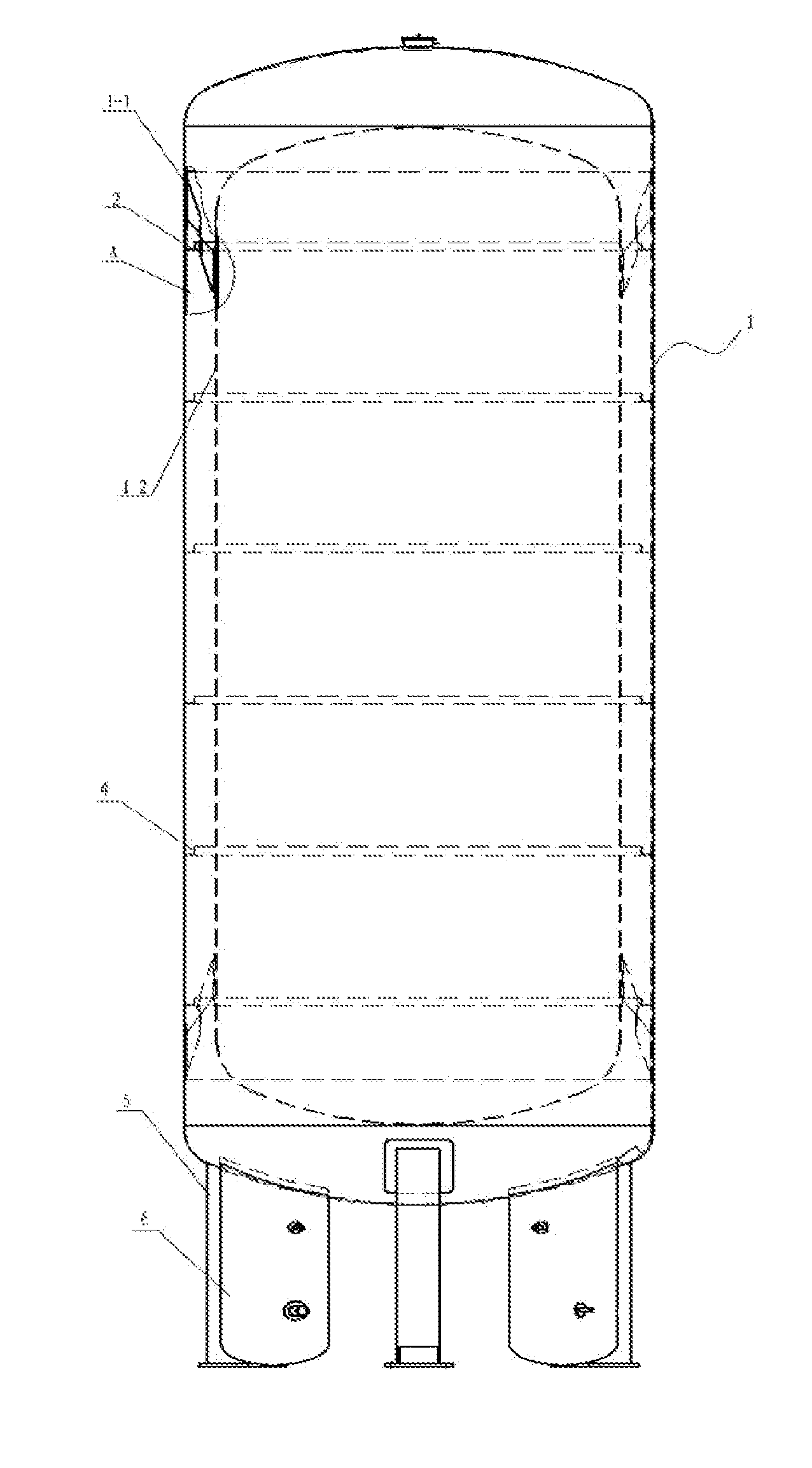
FIELD OF THE INVENTION [0001]The present invention relates to the field of storage and use of cryogenic liquids, and in particular, to an energy-efficient vertical cryogenic storage tank for storing liquefied natural gas.BACKGROUND[0002]A cryogenic storage tank is a cryogenic container for storing liquefied natural gas (LNG), liquid nitrogen, liquid oxygen, and other products, which generally comprises a housing, an inner container, and a vacuum insulation interlayer disposed between the housing and inner container. Additionally, there are straps disposed between the housing and inner container in order to maintain the strength and stability of the inner container.[0003]Daily evaporation rate of a cryogenic tank is generally 0.02%˜0.08% when the tank is full. The better insulation is of the tank, the lower cooling loss, and the smaller evaporation rate; when the evaporation rate increases, the burden on the evaporation gas compressor and refrigeration system increases as well, which...

Claims


Application Information

Patent Timeline
Patent Type & Authority Applications(United States)
IPC IPC(8): F17C13/00F17C3/08
CPCF17C13/001F17C3/08F17C2260/02F17C2221/033F17C2203/01F17C2201/0104F17C2201/032F17C2201/054F17C2203/016F17C2203/0391F17C2203/0629F17C2205/018F17C2221/011F17C2221/014F17C2223/0161F17C2223/033F17C2227/0339F17C2227/0374F17C2260/031F17C2270/0134F17C2270/05
Inventor ZHAI, LANHUIWANG, HONGXIADONG, MINGHUIPAN, XIAO'E
Owner SHIJIAZHUANG ENRIC GAS EQUIP
Learn More