
Foreign Object Detection Method for Wireless Charging Systems

a detection method and wireless charging technology, applied in the direction of batteries, exchanging data chargers, inductances, etc., can solve the problems of reducing the efficiency of arrangement and causing the heat of nearby conductive objects

Active Publication Date: 2015-11-05
GOOGLE LLC
View PDF8 Cites 13 Cited by
  • Summary
  • Abstract
  • Description
  • Claims
  • Application Information

AI Technical Summary

Benefits of technology

This patent is about a system that allows a transmitter to send out a special kind of pulse that a receiver can detect and reject. This is done by measuring the back electromagnetic field caused by the transmitted pulse. The system can determine how much power is being sent to loads other than the receiver, which can help to assess the quality of the transmission network. The patent also includes possible responses to the assessment, such as stopping or modifying the transmission. Overall, this technology can improve the efficiency and reliability of wireless communication.

Problems solved by technology

However, the magnetic fields may induce currents in nearby conductive objects such as metal based objects.
The result may be a reduced efficiency for the arrangement and may cause the nearby conductive objects to heat up as a result of the induced currents.

Method used


Image

  • Foreign Object Detection Method for Wireless Charging Systems
  • Foreign Object Detection Method for Wireless Charging Systems
  • Foreign Object Detection Method for Wireless Charging Systems

Examples


Embodiment Construction

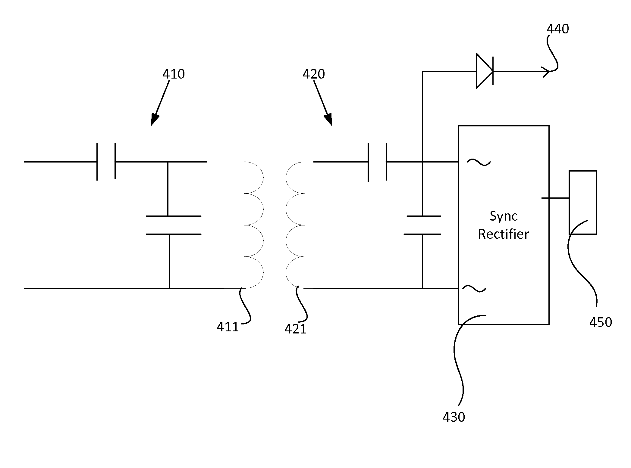
[0013]Traditional, wireless charging systems use alternating magnetic fields to transfer power between a transmitter and a receiver by inducing current in the receiver. These magnetic fields can also induce parasitic currents in nearby conductors, typically metal bodies, causing heating of the conductor and a loss of available power in the inductive charging system, thus reducing efficiency. It may be beneficial to know the amount of parasitic loss so that an appropriate response action can be taken based on the amount of loss. As an example, if the parasitic loss is an above a predetermined threshold, then the inductive power transfer may be placed on hold until the external conductor is removed from the environment. Parasitic loads may be unfavorable for any applicable reason such as an undesirable amount of wasted power, unsafe amount of heat transferred to the external conductor, and / or an insufficient amount of power provided to the receiver such that the receiving device canno...


PUM


Abstract

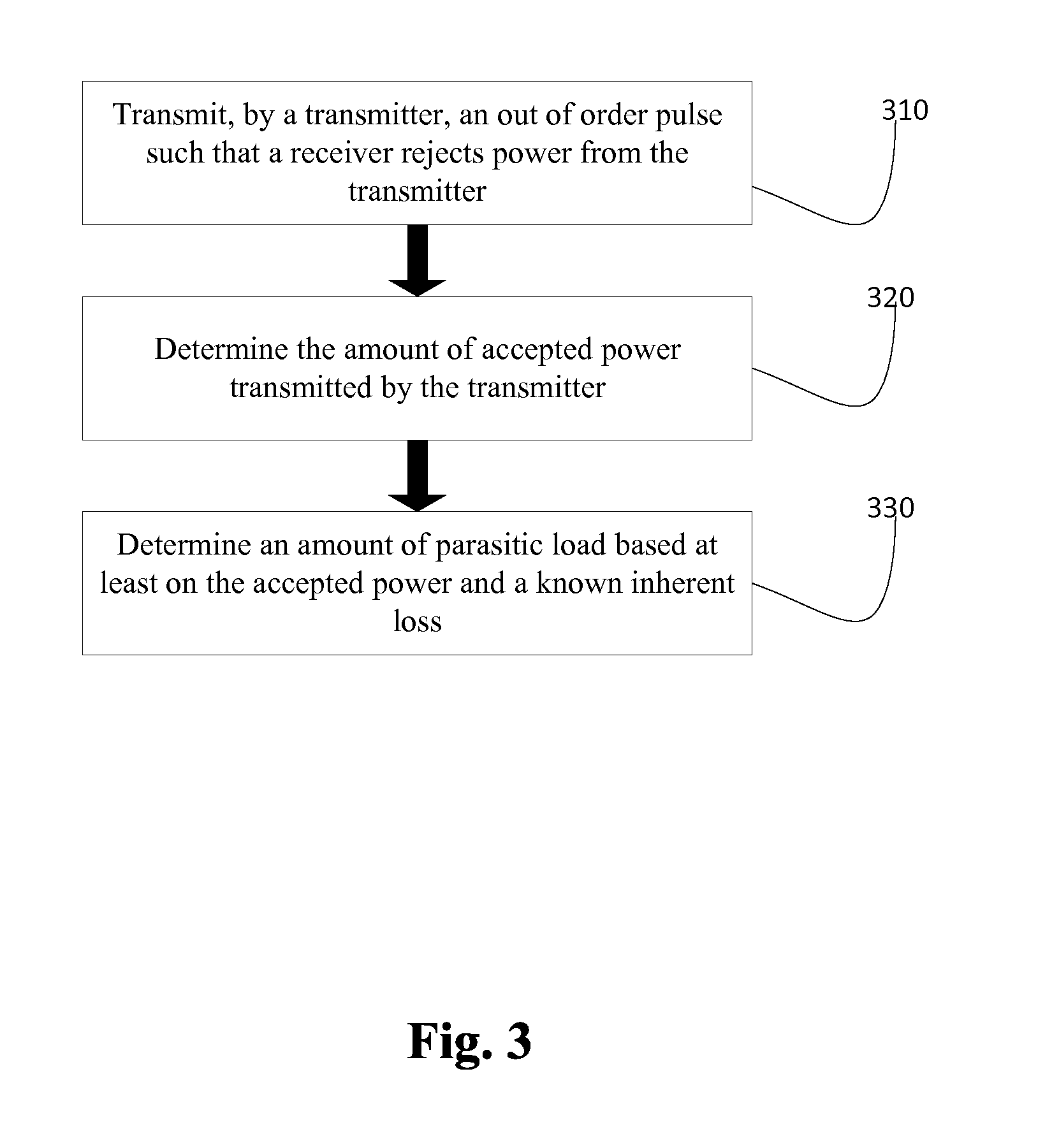
Systems, device and techniques are disclosed for measuring a parasitic load in an environment. A transmitter may transmit an out of order pulse such that a receiver with synchronous rectification circuitry rejects induced power from the transmitter based on the out of order pulse. The parasitic load is determined by measuring the amount of power induced by the transmitter while the intended receiver rejects the power subtracted by known inherent loss.

Description

BACKGROUND[0001]Traditionally, a wireless charging arrangement may use alternating magnetic fields to transfer power between a transmitter and a receiver by inducing current in the receiver. The induced current may be received by the receiver to operate a device (e.g., a mobile device) or to charge a battery, or both. However, the magnetic fields may induce currents in nearby conductive objects such as metal based objects. The result may be a reduced efficiency for the arrangement and may cause the nearby conductive objects to heat up as a result of the induced currents. As an example, an inductive charger may be configure to wirelessly charge a laptop while the inductive charger is placed within 5 feet of the laptop. As the inductive charger is wirelessly charging the laptop, a metal cup may also be within five feet of the inductive charger such that the metal cup draws charge from the inductive charger and heats up.BRIEF SUMMARY[0002]According to implementations of the disclosed s...

Claims


Application Information

Patent Timeline
Patent Type & Authority Applications(United States)
IPC IPC(8): H02J5/00
CPCH02J5/005H02J50/60H02J50/12H02J7/00034H02J7/00
Inventor BARTLETT, SCOTT
Owner GOOGLE LLC
Learn More