
Embedded Symmetric Multiple Axis Antenna System With Isolation Among The Multiple Axes

a multi-axis, antenna system technology, applied in loop antennas with ferromagnetic cores, polarised antenna unit combinations, instruments, etc., can solve the problems of inconvenient hand-held devices, inconvenient installation, and large antenna arrangements. , to achieve the effect of reducing cross coupling

Inactive Publication Date: 2015-11-05
GAN CORP
View PDF2 Cites 35 Cited by
  • Summary
  • Abstract
  • Description
  • Claims
  • Application Information

AI Technical Summary

Benefits of technology

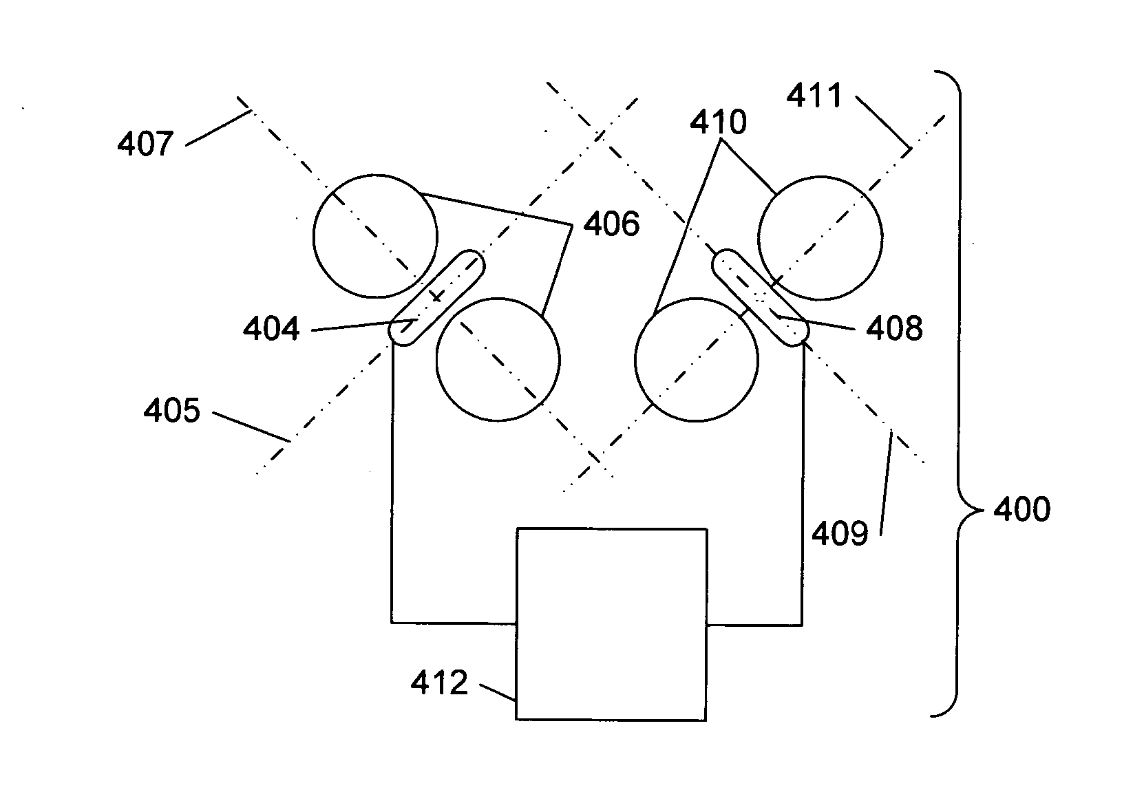
The present patent describes a three-axis magnetic antenna system with three identical magnetic antenna elements that are positioned symmetrically around a reference point. The magnetic axes from the three antenna elements are orthogonal to each other. This arrangement results in efficient packaging for small electronic devices. The system provides symmetrical omnidirectional coverage and guarantees orientation independence. A location system utilizing this antenna system is also described. Additionally, a moldable triple coil holder for the antenna system is described. The threeaxis antenna system offers numerous benefits and advantages, such as compact package size and efficient orientation coverage.

Problems solved by technology

When operated at “low” frequencies, traditional quarter-wavelength antennas become prohibitively large for certain applications.
For example, a quarter-wavelength monopole operating at 10 MHz has a physical size of 7.5 m. This may be acceptable for an outdoor antenna (for instance), but would be impractical for a compact hand-held device.
Existing antenna arrangements are large and bulky or small and inefficient.
Other existing antenna arrangements are prone to undesirable coupling to a mobile asset or person carrying an associated wireless device.

Method used


Image

  • Embedded Symmetric Multiple Axis Antenna System With Isolation Among The Multiple Axes
  • Embedded Symmetric Multiple Axis Antenna System With Isolation Among The Multiple Axes
  • Embedded Symmetric Multiple Axis Antenna System With Isolation Among The Multiple Axes

Examples


Embodiment Construction

Overview of the Invention

Orthogonal and Magnetic Antenna Basics

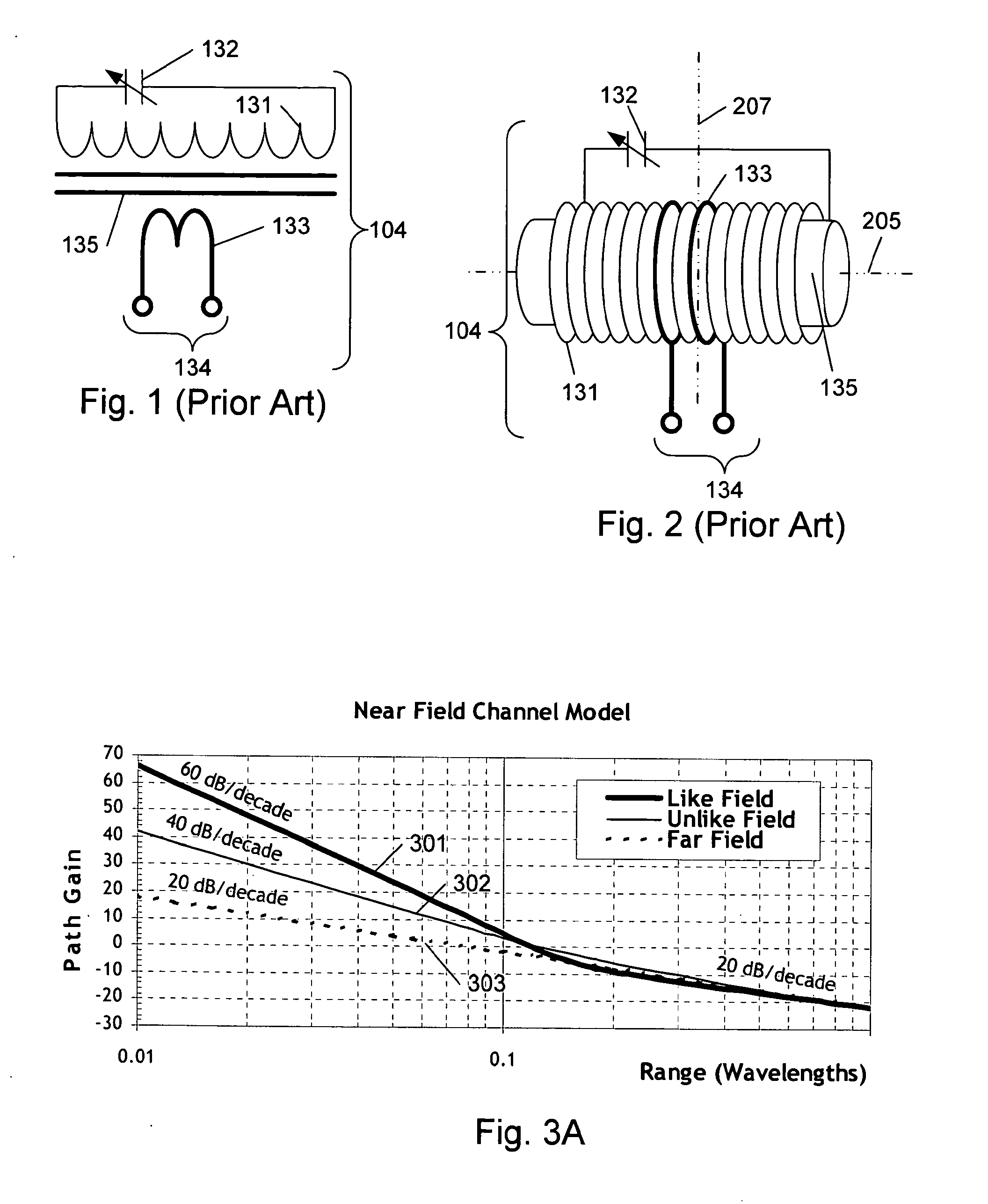
[0104]Applicants discovered that orthogonal magnetic antennas offer unique advantages for transmission and reception in near-field wireless systems and elsewhere. Details may be found in “Near-field location system and method,” (Ser. No. 11 / 272,533, filed Nov. 10, 2005, now U.S. Pat. No. 7,307,595, issued Dec. 11, 2007). Additional compact antenna designs are shown in applicant's “Space efficient magnetic antenna system,” (Ser. No. 11 / 473,595, filed Jun. 22, 2006, now U.S. Pat. No. 7,755,552 issued Jul. 13, 2010). Other antenna concepts of value in an wireless systems and elsewhere are disclosed in Applicant's co-pending “Planar loop antenna system,” (Ser. No. 12 / 857,528, Aug. 16, 2010 now U.S. Pat. No. 8,436,780 issued May 7, 2013), and “Space efficient magnetic antenna method,” (Ser. No. 12 / 834,821, filed Jul. 12, 2010, now U.S. Patent Publication U.S. 2010 / 0277387 published Nov. 4, 2010). Applicant's “Directive electr...


PUM

PropertyMeasurementUnit
Fractionaaaaaaaaaa
Fractionaaaaaaaaaa
Angleaaaaaaaaaa

Abstract

The present disclosure pertains to a rotationally triply symmetric three axis magnetic antenna system having substantial isolation among the three axes, including a three axis skew orthogonal magnetic antenna system and device utilizing the antenna system. The antenna system comprising three substantially identical magnetic antenna elements disposed symmetrically about a reference point such that the magnetic axes from the three antenna elements are orthogonal to one another in direction and do not intersect one another. The three antenna elements are positioned in a substantial cross coupling null from one another to minimize cross coupling. The arrangement yields packaging efficiency for compact electronic devices. A 1, 1, diameter embodiment is disclosed. A location system utilizing the antenna system is disclosed. Methods for producing the antenna are disclosed. A moldable triple coil holder for the antenna system is described.

Description

[0001]The present application is a continuation in part of application Ser. No. 12 / 834,821 titled: “Space Efficient Magnetic Antenna Method” filed Jul. 12, 2010 by Schantz et al, and the present application claims the benefit under 35 USC 119(e) of provisional application 61 / 838,422 titled: “Minimum coupling and symmetric antenna array” filed Jun. 24, 2013 by Schantz; Ser. No. 12 / 834,821 is a continuation in part of U.S. patent application Ser. No. 11 / 473,595 Titled: “Space Efficient Magnetic Antenna System”, filed Jun. 23, 2006 by Schantz et al, now U.S. Pat. No. 7,755,552, which is a continuation-in-part of U.S. patent application Ser. No. 11 / 272,533 titled: “Near field location system and method,” filed Nov. 10, 2005 by Schantz et al., now U.S. Pat. No. 7,307,595, which claims the benefit under 35 USC 119(e) of provisional application Ser. No. 60 / 637,779, titled: “Near field amplitude positioning system and method,” filed Dec. 21, 2004 by Schantz et al., all of which are incorpor...

Claims


Application Information

Patent Timeline
IPC IPC(8): H01Q21/28H01Q21/00H01Q7/00
CPCH01Q21/28Y10T29/49018H01Q21/0087H01Q7/00G01S5/14H01Q1/273H01Q1/276H01Q7/08H01Q21/24G01S5/02521
Inventor SCHANTZ, HANS GREGORYPITTMAN, CHRISTOPHER DAVIDRICHARDS, JAMES LEEWERNER, STEPHEN A.
Owner GAN CORP
Learn More