Artificial illumination device

a technology of artificial illumination and illumination device, which is applied in the direction of lighting and heating apparatus, lighting effects, decorative arts, etc., can solve the problems of devices not meeting the requirements of visual appearance, and preventing these illumination devices from faithfully achieving visual characteristics

Active Publication Date: 2015-11-05
COELUX
View PDF9 Cites 16 Cited by
  • Summary
  • Abstract
  • Description
  • Claims
  • Application Information

AI Technical Summary

Benefits of technology

[0016]According to an embodiment, an artificial illumination device for generating natural light similar to that from the sun and the sky with making an observer experience a visual infinite-depth perception of a sky and sun image when the observer directly looks at the artificial illumination device may have: a direct-light source which includes a first light-emitting device and a first emitting surface and is configured so that the direct-light source produces a direct light with a luminance profile Ldirect(x, y, θ, φ) which has—with respect to angular dependence on polar angle θ—a narrow peak in the angular distribution around a direct-light direction and a low background, and is—with respect to spatial coordinates—uniform across the first emitting surface, and a diffused-light generator which is positioned downstream of the first light-emitting device, and is at least partially light-transparent, and is configured to cause diffused light at a second emitting surface, wherein one of the first emitting surface and the second emitting surface is positioned downstream with respect to the other or both coincide to form an outer emitting surface of the artificial illumination device, and wherein the artificial illumination device is configured such that the direct-light source and the diffused-light generator co-operate to form outer light at the outer emitting surface which includes a first light component which propagates along

Problems solved by technology

This fact thus prevents these illumination devices from faithfully achieving the visual characteristics of an ambient illuminated by natural light.
Moreover, these devices do not properly satisfy the requirements concerning th

Method used


Image

  • Artificial illumination device
  • Artificial illumination device
  • Artificial illumination device

Examples


Embodiment Construction

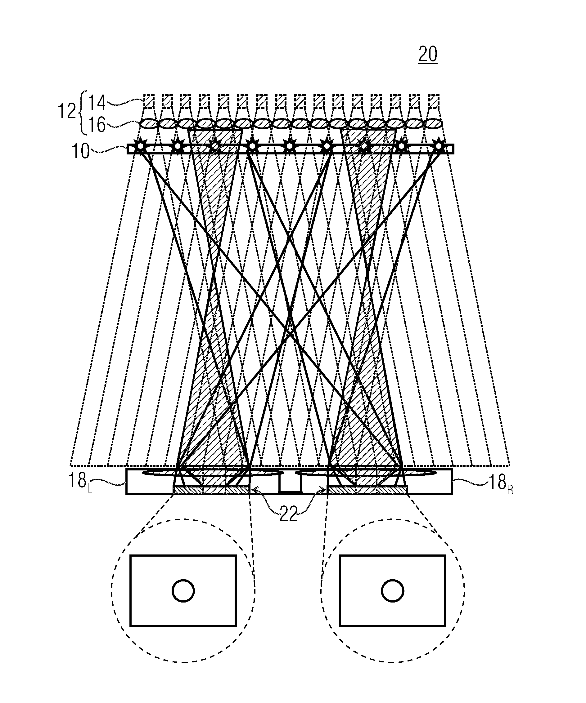
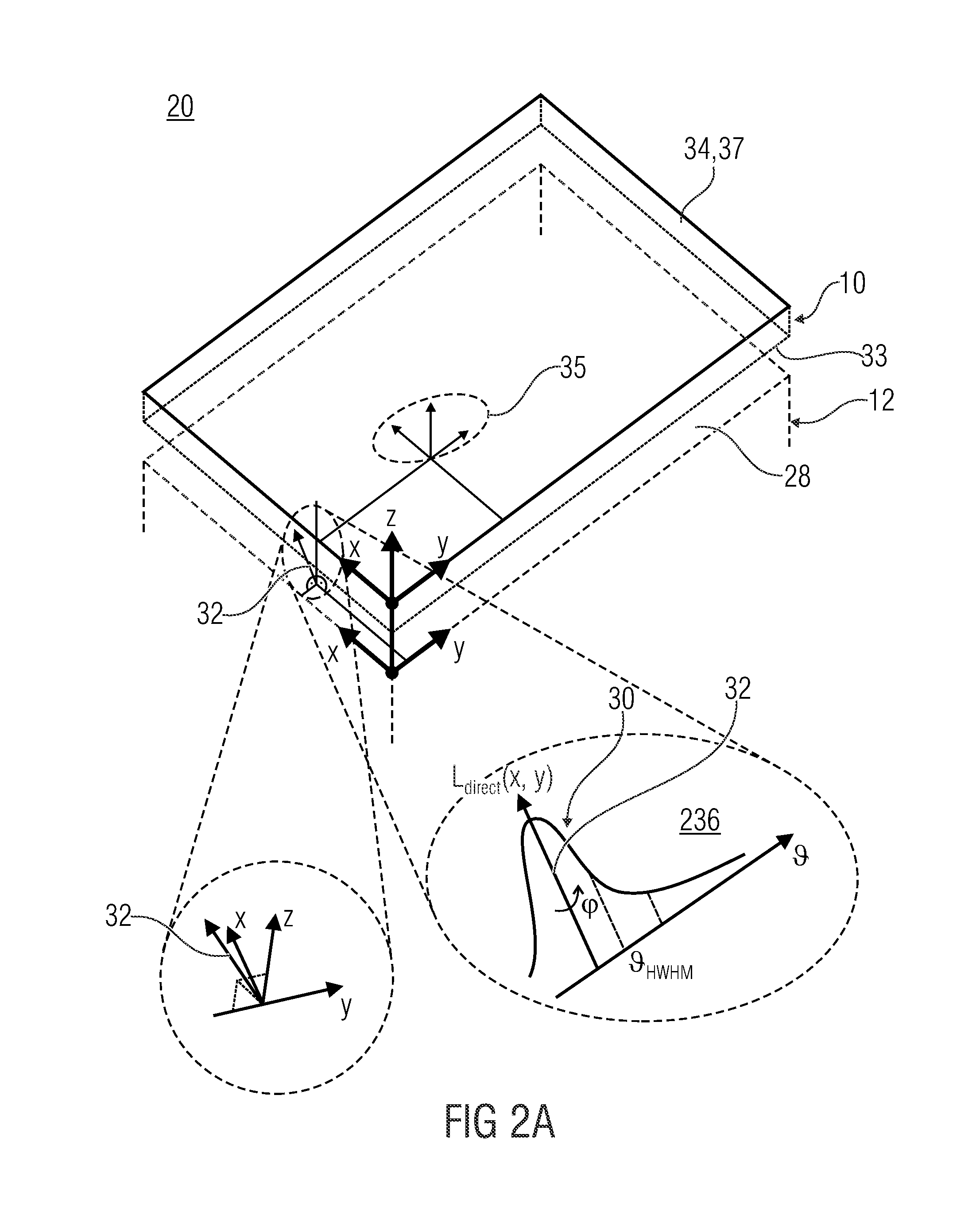
[0085]As already introduced, the perception of natural illumination from sky and sun relies on the one side on the light emitted by the illumination device, which should feature a direct-light component highly collimated with low CCT, mimicking the light from the sun, and a higher CCT diffused-light component, mimicking the illumination effect of the sky, such that the direct-light component is able to cast sharp parallel shadows of the objects illuminated by the illumination device and the diffused-light component gives a bluish color to such shadows. On the other side, the perception of natural illumination from sky and sun relies on the perception of infinite depth of the sky and sun images when directly viewing at the illumination device itself.

[0086]The capability of an observer to evaluate the distance of objects, and therefore the depth of the views that constitute a three-dimensional scenery, is based on multiple physiological and psychological mechanisms connected to focusi...


PUM


Abstract

An artificial illumination device for generating natural light similar to that from the sun and the sky includes a direct-light source; and a diffused-light generator, wherein the direct-light source includes a first light-emitting device configured to emit a primary light, and a first emitting surface positioned downstream the first light-emitting device, wherein the diffused-light generator is at least partially light-transparent and is positioned downstream of the first light-emitting device and includes a second emitting surface and is configured to cause diffused light at the second emitting surface. Both co-operate to form outer light at an outer emitting surface which includes a first light component which propagates along directions contained within the narrow peak and a second light component which propagates along directions spaced apart from the narrow peak, and wherein the first light component has a CCT which is lower than a CCT of the second light component.

Description

CROSS-REFERENCE TO RELATED APPLICATIONS[0001]This application is a continuation of copending International Application No. PCT / EP2012 / 072648, filed Nov. 14, 2012, which is incorporated herein by reference in its entirety.BACKGROUND OF THE INVENTION[0002]The present invention is concerned with artificial illumination devices which realize the perception of the natural light from the sun and the sky.[0003]More precisely, the perception of the natural light from the sky and the sun is related both to the capacity of the illumination device to illuminate an ambient with effects very similar to the effects that would manifest in the same room if an aperture with sky and sun beyond it, i.e. a window, would be positioned at the same place, and also to the appearance of the device itself when directly viewing at it, which creates the visual appearance of infinite depth for the sky and infinite position of the sun sources.[0004]Therefore the aims which the embodiments of the present inventio...

Claims


Application Information

Patent Timeline
IPC IPC(8): F21V9/02F21V5/00F21V8/00
CPCF21V9/02G02B6/0046F21V5/004F21Y2101/02F21V5/008F21Y2105/001F21V5/007F21S8/006F21V5/04F21V5/045F21S8/00F21Y2115/10F21Y2105/10F21W2121/00F21W2121/008F21S8/06
Inventor DI TRAPANI, PAOLOMAGATTI, DAVIDE
Owner COELUX
Why Eureka
Try Eureka