Production plant for forming engineered composite stone slabs

a technology of engineered stone and production plant, which is applied in the field of engineered stone slabs, can solve the problems of not being able to automatically return the slab-supporting tray or the mold to the mixer, and achieve the effects of low energy efficiency, high pressing force, and high vibration energy

Active Publication Date: 2015-11-05
GRP IND FOURNIER INC
View PDF0 Cites 29 Cited by
  • Summary
  • Abstract
  • Description
  • Claims
  • Application Information

AI Technical Summary

Problems solved by technology

As a consequence, there is no practical way to automatically return slab-supporting trays or molds to the mixer.

Method used


Image

  • Production plant for forming engineered composite stone slabs
  • Production plant for forming engineered composite stone slabs
  • Production plant for forming engineered composite stone slabs

Examples


Embodiment Construction

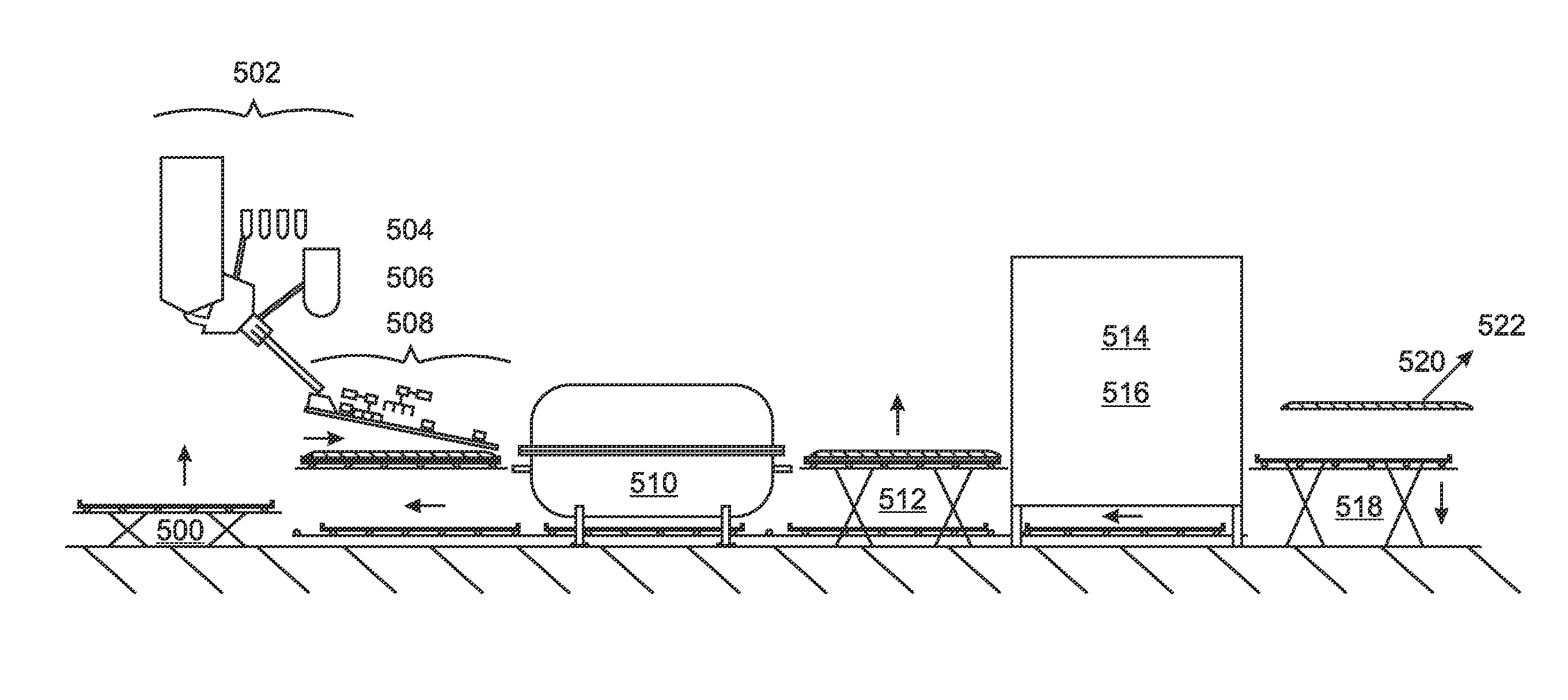
[0139]A production plant for making engineered stone slabs and other engineered stone products costs less to manufacture and install, provides shorter press cycle times, and requires less energy consumption and maintenance as compared to a Breton engineered stone production plant. Embodiments further allow relatively easy and inexpensive changing of the esthetic coloring applications and / or of the slab size being produced.

[0140]With reference to FIG. 4, these advantages are enabled at least partly by features of the VVP press 400 used in embodiments of the invention, which replaces the entire 350+ ton inertial base 222,214 of the Breton press design 208 with a lightweight vibration table 406B below the slab 126 and a second vibrating device 404B below the table, in addition to the pressing plate 406A and upper vibration device 404A above the slab 126. In the embodiment of FIG. 4, a mounting bracket 410 supports the vibration table 406B, and in turn is supported by a vibration dampin...


PUM

PropertyMeasurementUnit
sizesaaaaaaaaaa
particle sizeaaaaaaaaaa
thicknessaaaaaaaaaa

Abstract

An engineered stone production plant includes a vacuum vibration press (“VVP”) suspended above the ground, so that a conveyor belt and / or returning empty trays or molds from a curing oven to a mixing station can pass beneath the VVP. Rigid, self-supporting trays or molds can convey slabs through the plant on rollers, which allow independent horizontal movement of the slabs during spreading and coloring / veining of the slab mixture. Embodiments include air levitation for transporting slabs into and out of the VVP. The curing oven can be air-heated. The pressing plate can be sealed with the tray or mold by walls that extend downwardly from the press plate over a flexible covering sheet, by a gasket surrounding the pressing plate, or by an angle strip surrounding the slab mixture. In embodiments, the slab size can be changed by exchanging elastomeric mold walls, or by exchanging molds and pressing platens.

Description

RELATED APPLICATIONS[0001]This application is a US Bypass of PCT Application No. PCT / US15 / 40154 filed on Jul. 13, 2015. This application is also a continuation in part of U.S. application Ser. No. 14 / 729,823, filed on Jun. 3, 2015. U.S. application Ser. No. 14 / 729,823 is a continuation in part of U.S. application Ser. No. 14 / 222,695, filed on Mar. 24, 2014, now issued U.S. Pat. No. 9,073,239. U.S. application Ser. No. 14 / 222,695 is a continuation in part of U.S. application Ser. No. 13 / 875,691, filed on May 2, 2013, which is a continuation in part of PCT Application No. PCT / US2012 / 051817, filed on Aug. 22, 2012, which claims the benefit of U.S. Provisional Application No. 61 / 526,308, filed Aug. 23, 2011. U.S. application Ser. No. 13 / 875,691 also claims the benefit of U.S. Provisional Application No. 61 / 767,272, filed on Feb. 21, 2013. All of these applications are herein incorporated by reference in their entirety for all purposes.FIELD OF THE INVENTION[0002]The invention relates to...

Claims


Application Information

Patent Timeline
Patent Type & Authority Applications(United States)
IPC IPC(8): B28B1/08B28B3/02
CPCB28B3/022B28B1/082B29C67/244B30B11/022B30B15/0076B28B1/081B30B15/024B30B15/026B28B1/087
Inventor BANUS, CHRISTOPHER T.
Owner GRP IND FOURNIER INC
Why Eureka
Try Eureka