
Method of manufacturing a metallic component from individual units arranged in a space filling arrangement

Inactive Publication Date: 2015-10-22
EUROPEAN SPACE AGENCY
View PDF6 Cites 0 Cited by
  • Summary
  • Abstract
  • Description
  • Claims
  • Application Information

AI Technical Summary

Benefits of technology

The present invention provides a method for manufacturing metallic components with their final shape without the need for difficult modelling. This method also improves the fly-to-buy ratio and allows for higher complexity in geometrical shape and material compositions than traditional manufacturing methods.

Problems solved by technology

Furthermore, it does not exclude that small gaps may exist between substantially parallel side surfaces of neighboring units resulting from irregularities in the manufacturing thereof.

Method used


Image

  • Method of manufacturing a metallic component from individual units arranged in a space filling arrangement
  • Method of manufacturing a metallic component from individual units arranged in a space filling arrangement
  • Method of manufacturing a metallic component from individual units arranged in a space filling arrangement

Examples


Embodiment Construction

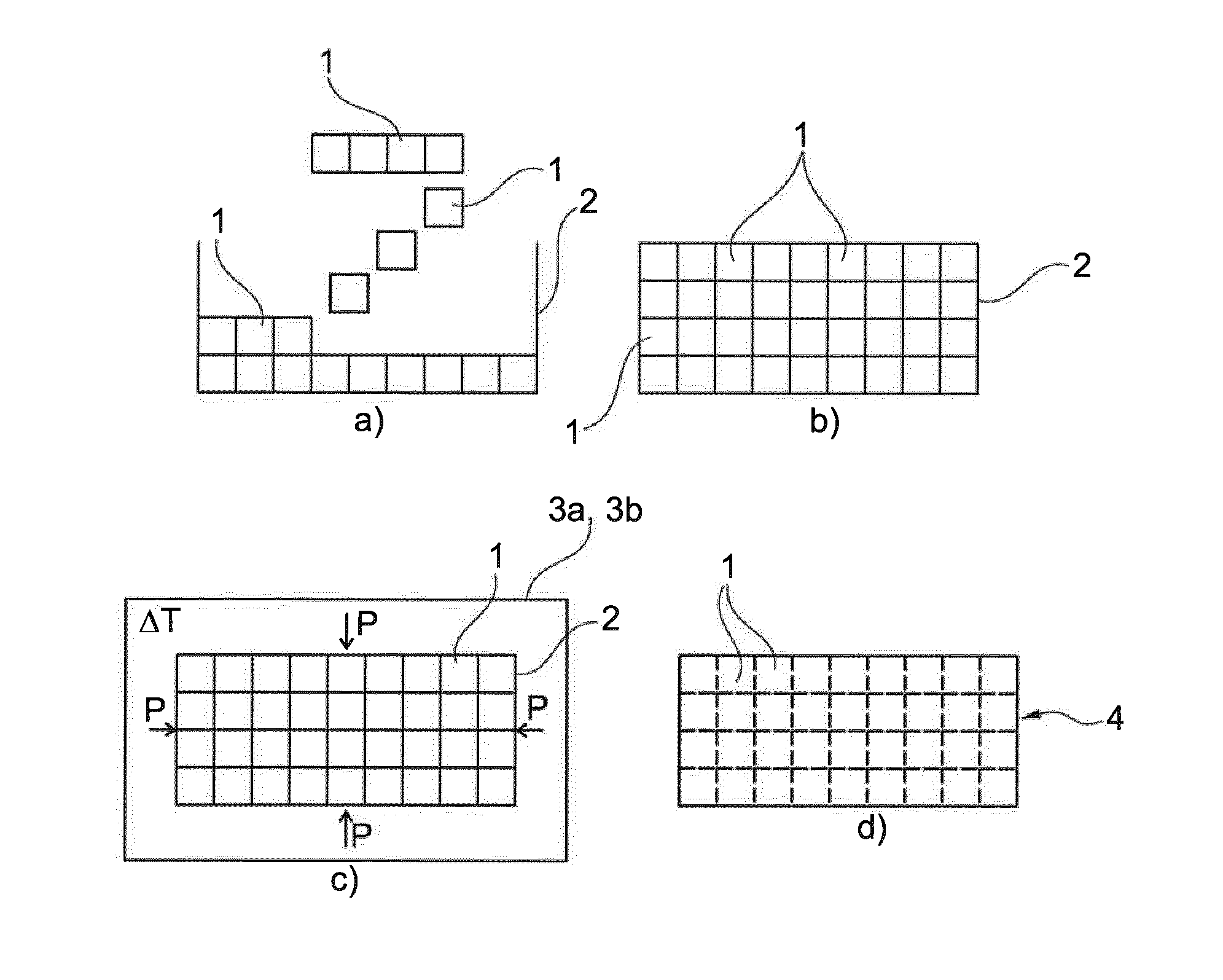
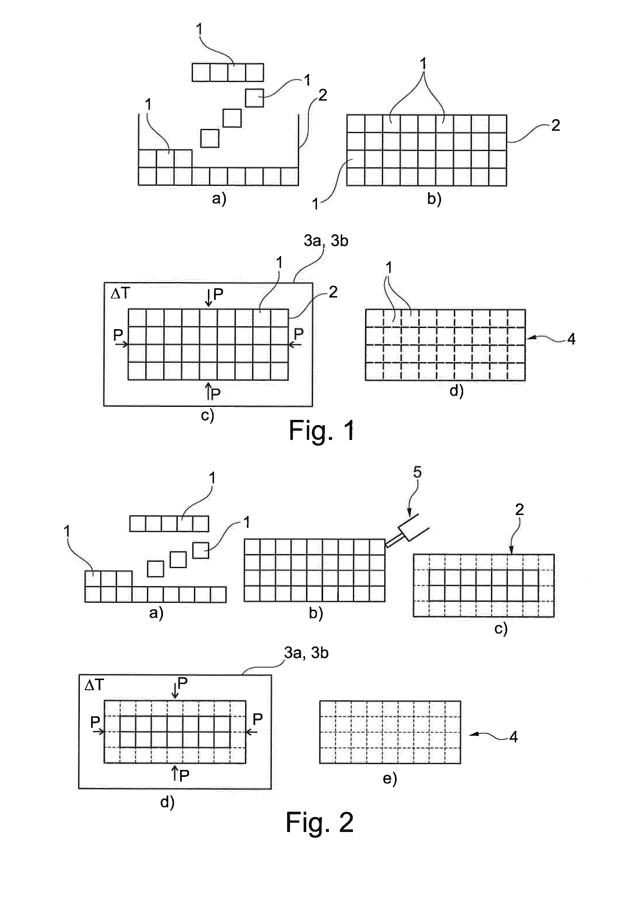
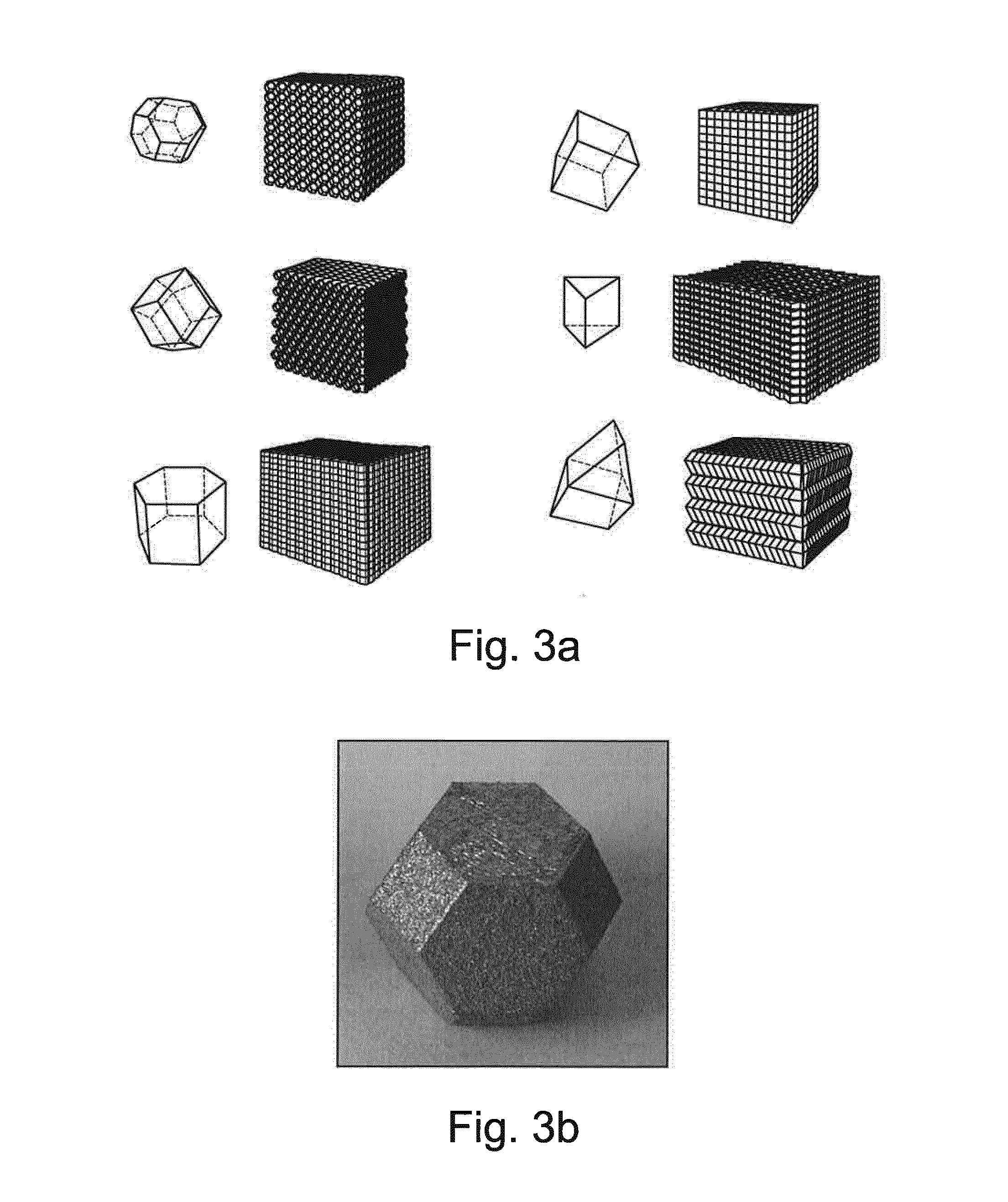
[0057]FIG. 1 shows schematically the overall steps in a method according to the invention. The method comprises arranging a plurality of individual units 1 in a space-filling arrangement in a canister 2 as shown in FIG. 1.a. In the figure some of the not yet arranged units 1 are shown separated from each other and others are shown aligned to illustrate that both of these ways of arranging can be used either alone or in combination. Possible ways of doing so will be explained below. FIG. 1.b shows the canister 2 comprising the not yet joined units 1 which are shown in these and the following figures as being cubic for illustrative purposes only. The actual shape used may be any shape that allows the units 1 to be arranged in a space-filling arrangement. The shape of at least a majority of the units 1 may e.g. be selected from the group consisting of cubes, truncated octahedra, rhombic dodecahedra, hexagonal and triangular prisms, gyrobifastigia or combinations thereof.

[0058]The canis...


PUM

PropertyMeasurementUnit
Lengthaaaaaaaaaa
Temperatureaaaaaaaaaa
Timeaaaaaaaaaa

Abstract

The present invention relates to a method of manufacturing a metallic component 4 from a plurality of individual units 1 which are arranged in a space-filling arrangement in a canister 2. The canister will typically be a separate container, but it may also an endogenous canister obtained by applying laser welding 5 to individual units 1 arranged adjacent to outer surfaces of the arrangement so that these units 1 are joined to form a shell of units 1 which constitute the canister 2. Then heat and either high pressure or vacuum is applied so that at least a majority of the units 1 are diffusion bonded together to form a rigid metallic component 4. Heat and high pressure may be applied by a hot isostatic press 3a, and alternatively heat and vacuum may be applied by using a vacuum furnace 3b.

Description

CROSS-REFERENCE TO RELATED APPLICATIONS[0001]This application is the U.S. national stage application of International Patent Application No. PCT / EP2012 / 074080, filed Nov. 30, 2012, which is hereby incorporated by reference.FIELD OF THE INVENTION[0002]The present invention relates to a method of manufacturing a metallic component and in particular to a method comprising the step of arranging a plurality of individual units in a space-filling arrangement.BACKGROUND OF THE INVENTION[0003]Metallic components can be manufactured by a number of processes including machining, such as CNC milling. A factor often referred to within the aerospace community is the buy-to-fly ratio which is the amount of material that is actually flown in the aerospace component divided by the amount of material purchased by the manufacturer; i.e. a measure of how much material you need to purchase in order to manufacture the final component. For example, a CNC machined part would have a typical fly-to-buy rati...

Claims


Application Information

Patent Timeline
IPC IPC(8): B23K20/02B28B3/00
CPCB23K20/02B28B3/00B23K20/023B23K20/021B28B3/003B28B3/025B30B11/001
Inventor VOICE, WAYNE ERICJARVIS, DAVID JOHN
Owner EUROPEAN SPACE AGENCY
Learn More