
Sleep apnea diagnosis system and method of generating information using non-obtrusive audio analysis

a technology of sleep apnea and diagnosis system, applied in the field of sleep apnea diagnosis system and method, can solve the problems of excessive tiredness, deprived of restorative sleep, and devices that are still too expensive and obtrusiv

Active Publication Date: 2015-10-22
KONINKLJIJKE PHILIPS NV
View PDF6 Cites 2 Cited by
  • Summary
  • Abstract
  • Description
  • Claims
  • Application Information

AI Technical Summary

Benefits of technology

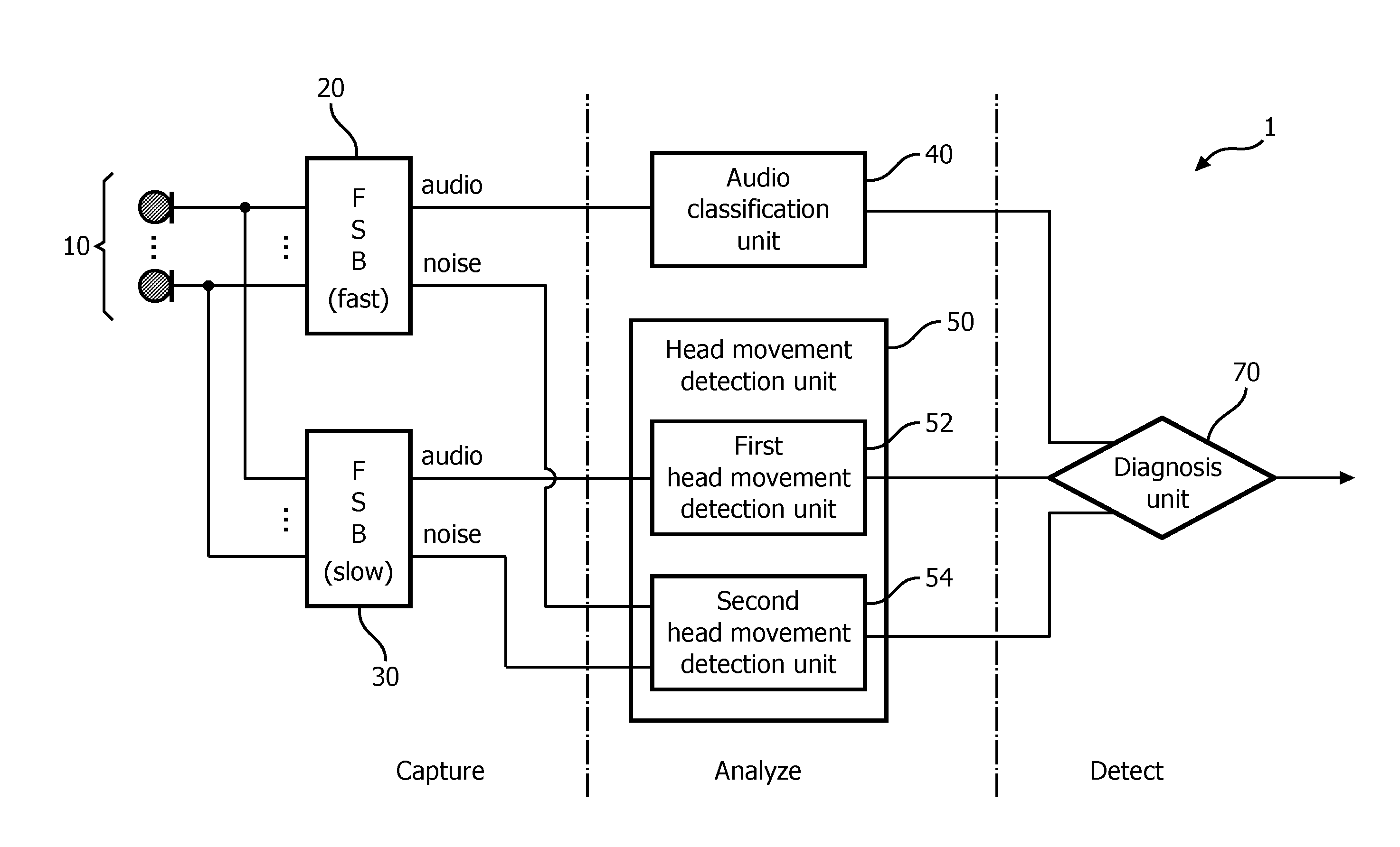
The patent describes an electronic device that uses microphones to detect sounds made by a patient with sleep apnea. The device has two beamformers that adjust to the patient's speed and create two sets of audio information, one with the first noise and one with the second noise. The device also analyzes the audio information and detects head movement. When combined, this information helps diagnose sleep apnea. The technical effect of the patent is the improved detection of snoring and apnea through the use of advanced technology.

Problems solved by technology

Because their sleep is constantly disrupted, they are deprived of the restorative sleep necessary for efficient functioning of body and mind.
OSA also causes excessive tiredness.
However, a PSG requires special hospital or sleep disorder center over-night stays with technicians present to monitor both the equipment and the patient.
While these devices are less expensive than a PSG, the devices are still too expensive and obtrusive.
However, although questionnaires and tests are cost-free and easy to take, their accuracy in assessing sleep apnea is very limited.
While audio recording can be accomplished inexpensively and non-obtrusively, the audio recording is sensitive to noise such as ambient noise, a snoring partner, or other noises, thus reducing the accuracy of the technique.

Method used


Image

  • Sleep apnea diagnosis system and method of generating information using non-obtrusive audio analysis
  • Sleep apnea diagnosis system and method of generating information using non-obtrusive audio analysis
  • Sleep apnea diagnosis system and method of generating information using non-obtrusive audio analysis

Examples


Embodiment Construction

[0018]As used herein, the singular form of “a”, “an”, and “the” include plural references unless the context clearly dictates otherwise. As used herein, the statement that two or more parts or components are “coupled” shall mean that the parts are joined or operate together either directly or indirectly, i.e., through one or more intermediate parts or components, so long as a link occurs. As used herein, “directly coupled” means that two elements are directly in contact with each other. As used herein, “fixedly coupled” or “fixed” means that two components are coupled so as to move as one while maintaining a constant orientation relative to each other.

[0019]Directional phrases used herein, such as, for example and without limitation, top, bottom, left, right, upper, lower, front, back, and derivatives thereof, relate to the orientation of the elements shown in the drawings and are not limiting upon the claims unless expressly recited therein.

[0020]As used herein, the phrase “adaptab...


PUM


Abstract

An electronic apparatus includes an array of microphones for detecting audible sounds generated by a patient and for generating audio information representing the detected audible sounds, a first beamformer having a first adaptability speed and configured to generate first audio information and first noise information from the audio information, a second beamformer having a second adaptability speed which is slower than the first adaptability speed, the second adaptive beamformer configured to generate second audio information and second noise information from the audio information, an audio classification unit for generating audio classification information based on the first audio information, a head movement detection unit for generating head movement information based on at least one of the second audio information, the first noise information, and the second noise information, and a diagnosis unit for determining a sleep apnea diagnosis based on the audio classification information and the head movement information.

Description

BACKGROUND OF THE INVENTION[0001]1. Field of the Invention[0002]The present invention pertains to sleep apnea diagnosis, and, in particular, to a sleep apnea diagnosis system and method.[0003]2. Description of the Related Art[0004]Obstructive sleep apnea (OSA) is a condition that affects millions of people from around the world. OSA is characterized by disturbances or cessation in breathing during sleep. OSA episodes result from partial or complete blockage of airflow during sleep that lasts at least 10 seconds and often as long as 1 to 2 minutes. In a given night, people with moderate to severe apnea may experience complete or partial breathing disruptions as high as 200-500 per night. Because their sleep is constantly disrupted, they are deprived of the restorative sleep necessary for efficient functioning of body and mind. This sleep disorder has also been linked with hypertension, depression, stroke, cardiac arrhythmias, myocardial infarction and other cardiovascular disorders. ...

Claims


Application Information

Patent Timeline
Patent Type & Authority Applications(United States)
IPC IPC(8): A61B5/00A61B5/087A61B7/00H04R1/08A61B5/11
CPCA61B5/4818H04R1/08A61B5/11A61B2562/04A61B7/003A61B5/087A61B5/7207H04R1/406H04R2410/01H04R3/005H04R2430/23
Inventor TRIKI, MAHD
Owner KONINKLJIJKE PHILIPS NV
Learn More