
Injector element

a technology of injectors and elements, applied in the field of injectors, can solve the problems of degrading quality, difficulty in changing geometrical parameters, and less and achieve the effect of more uniform mixing of propellants

Inactive Publication Date: 2015-10-15
SN DETUDE & DE CONSTR DE MOTEURS DAVIATION S N E C M A
View PDF5 Cites 4 Cited by
  • Summary
  • Abstract
  • Description
  • Claims
  • Application Information

AI Technical Summary

Benefits of technology

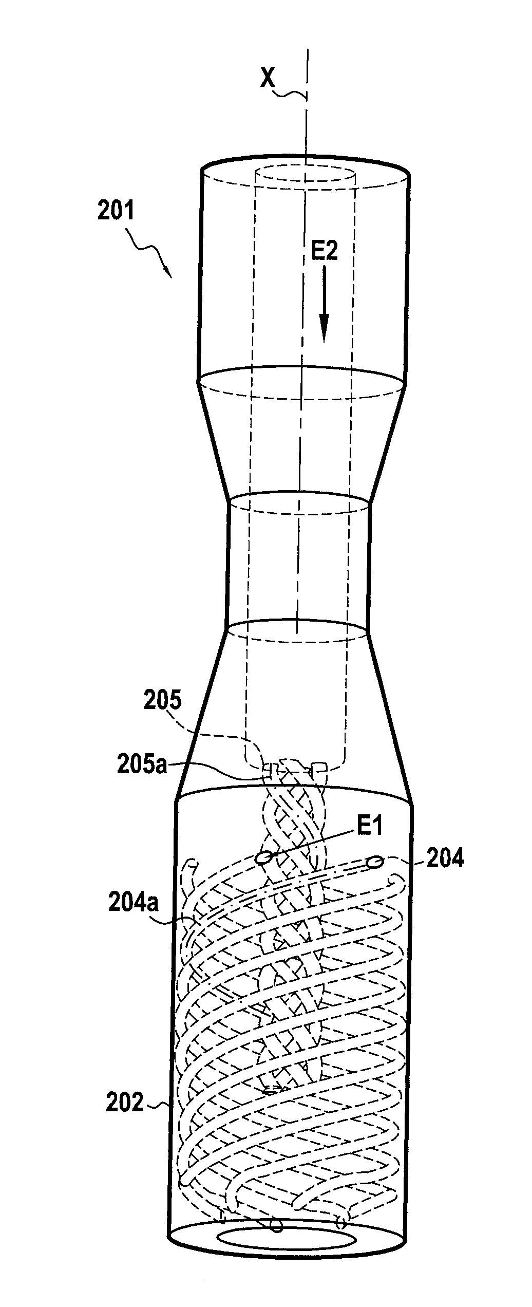
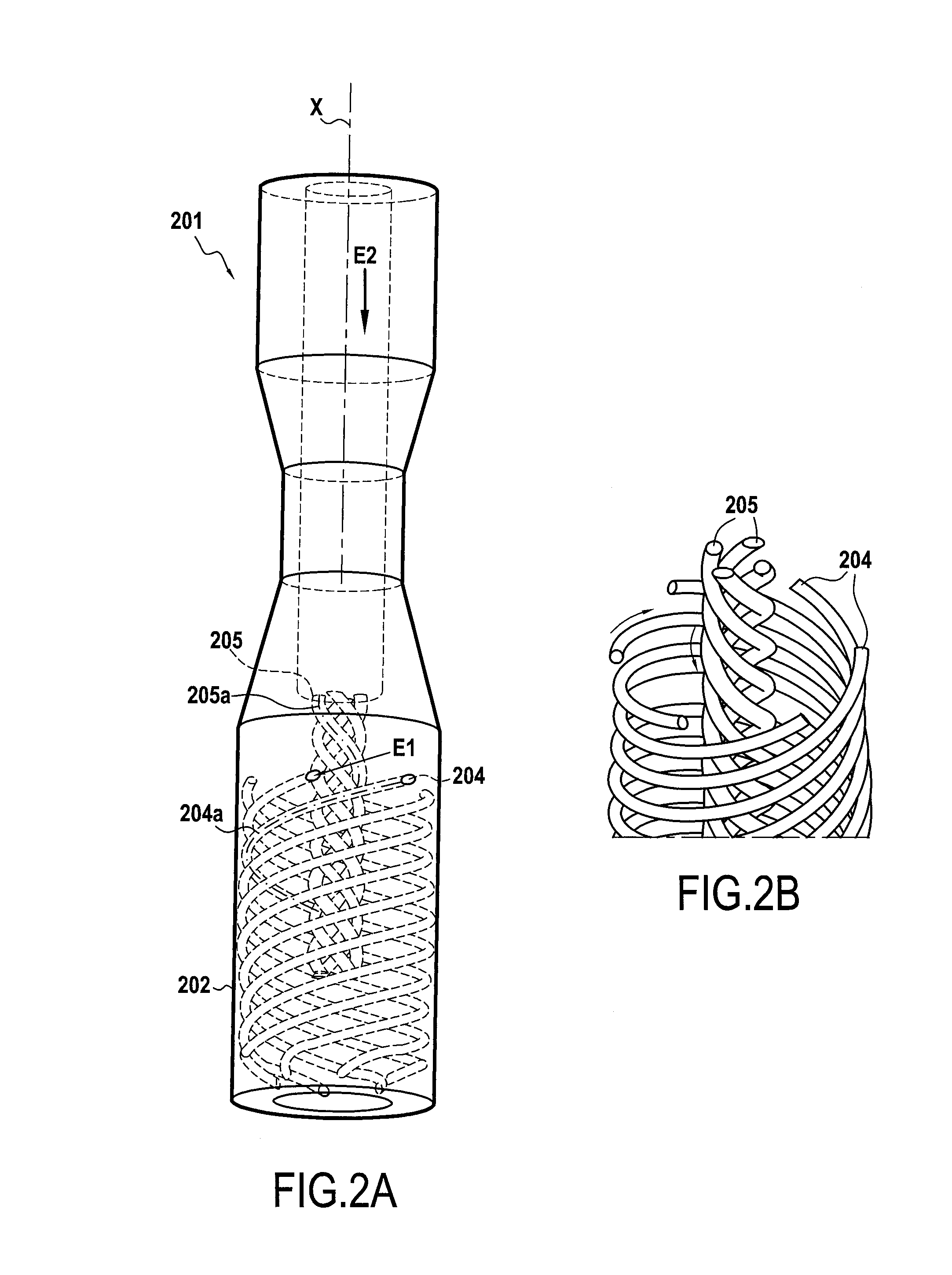
The present invention proposes an injector element for mixing propellants in a combustion chamber. The injector element has two helical channels, each with a center line following a respective helix centered on a central axis. The helices of the channels are situated inside each other, creating a point of intersection closer to the central axis in the second channel. This arrangement encourages better mixing of the propellants. The helices can be circular or conical, and may have non-circular sections twisted around the helix. The helices of both channels may turn in opposite directions, which increases turbulence and improves mixing downstream from the injector element. The injector element can be made more robust and has optimum section for better mixing with reduced head loss by being formed inside a single-piece part produced by additive fabrication.

Problems solved by technology

Nevertheless, starting from that basic concept, difficulties are encountered in changing the geometrical parameters in order to increase the individual power of each injector element without degrading the quality of the injection and of the combustion.
With greater flow rates, the mixing becomes less uniform and the quality of combustion degrades.

Method used


Image

  • Injector element
  • Injector element
  • Injector element

Examples


Embodiment Construction

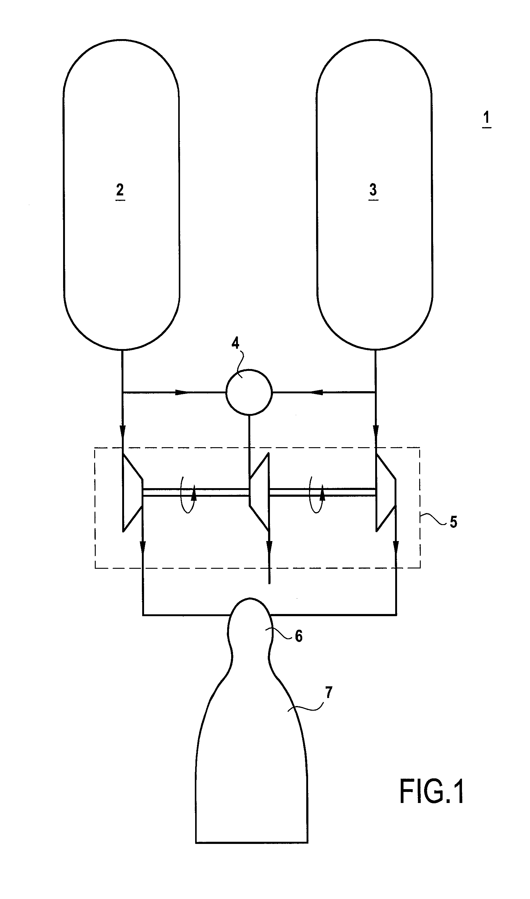
[0030]FIG. 1 is a diagram showing a rocket engine 1 having liquid propellants, and in particular cryogenic liquid propellants. The rocket engine 1 has a tank 2 for the first propellant, a tank 3 for the second propellant, a gas generator 4 fed by the first and second propellants, a turbopump 5 actuated by combustion gas coming from the gas generator 4, a main combustion chamber 6 fed with propellants by the turbopump 5, and a converging-diverging nozzle 7 for thrust ejection of the combustion gas generated in the main combustion chamber 6.

[0031]In order to obtain efficient combustion both in the gas generator 4 and in the main combustion chamber 6, these components have injector members for injecting propellants that make it possible to obtain a uniform mixture and distribution of the propellants. Typically, these injector members are in the form of injectors comprising an injector plate having a plurality of injector elements for the two propellants arranged therein.

[0032]FIGS. 2A ...


PUM


Abstract

The invention relates to the field of injectors, and in particular to an injector element (201) having at least one first helical channel (204) and at least one second helical channel (205), each of said helical channels (204, 205) following a respective helix (204a, 205a) centered on a central axis (X) of the injector element (201). The helix (205a) of the at least one second helical channel (205) is situated inside the helix (204a) of the at least one first helical channel (204).

Description

BACKGROUND OF THE INVENTION[0001]The present invention relates to the field of injectors, and in particular to elements for injecting a mixture of at least two propellants into a combustion chamber, such as for example a combustion chamber of a rocket engine.[0002]Patent document FR 2 712 030 A1 describes a two-propellant injector for injecting into a rocket engine combustion chamber, which injector has a feed structure in which the two propellants feed a plurality of injector elements arranged parallel to one another in an axisymmetric configuration over the surface of a circular injector plate structure that forms part of the injector. Such an injector plate may also be associated with quite a large number of injector elements, for example as many as one hundred or more, with their individual flow rates being combined in order to deliver the total flow rate for the engine.[0003]In that prior art injector, each injector element has a first channel for injecting the first propellant...

Claims


Application Information

Patent Timeline
IPC IPC(8): F02K9/52
CPCF02K9/52F05D2250/25F05D2240/127
Inventor TALIERCIO, LAETITIAINDERSIE, DOMINIQUE
Owner SN DETUDE & DE CONSTR DE MOTEURS DAVIATION S N E C M A
Learn More