Axial Piston Machine Utilizing A Bent-Axis Construction With Slippers On The Drive Flange

a technology of axial piston machine and drive flange, which is applied in the direction of reciprocating piston engine, positive displacement liquid engine, engine with rotating cylinder, etc., can solve the problem of limiting the maximum allowable speed of rotation of the axial piston machine, increasing the loss of hydraulic fluid, and correspondingly large tapered roller bearings to achieve a sufficiently long useful life. , to achieve the effect of high rotation speed, low construction effort or expense, and high torqu

Inactive Publication Date: 2015-10-08
LINDE HYDRAULICS
View PDF1 Cites 0 Cited by
  • Summary
  • Abstract
  • Description
  • Claims
  • Application Information

AI Technical Summary

Benefits of technology

This patent is about an invention of an axial piston machine that solves the problem of tipping in high-speed rotation. The invention uses a bent-axis construction with slippers that are mounted in an articulated manner in the drive flange to compensate for the centrifugal force acting on the slippers. This compensating force prevents tipping moments and allows the machine to rotate at high speeds while maintaining high efficiency. The invention also prevents an increase in leakage at the hydrostatic relieved sliding bearing and ensures stable operation of the machine.

Problems solved by technology

On account of the high axial forces to be absorbed, these two tapered roller bearings are correspondingly large to achieve a sufficiently long useful life.
However, large bearings of this type occupy a great deal of space and, on account of the high inertial forces that occur, limit the maximum allowable speed of rotation of the axial piston machine.
Tipping of this type leads to an opening of the seal gap on the hydrostatically relieved sliding bearing and to a resulting increased loss of hydraulic fluid by leakage on the hydrostatic sliding bearing.
One disadvantage of these axial piston machines, however, is that the torque connection necessary for the transmission of torque between the drive flange and the driveshaft entails a great deal of extra construction effort and expense and is complicated to manufacture.
On account of the high stresses and loads that occur in the torque connection, which can be in the form of a spline shaft gearing, the maximum torque that can be transmitted at the torque connection, which equals the output torque of the axial piston machine, is limited.
In addition, on account of the drive flange that is provided with pressure pockets, it is not possible to compensate for irregularities in the housing-side sealing surface that result from component deformations as a result of the pressure applied.
An articulated bearing system for the slipper in the drive flange is necessary because a correct orientation of the drive flange with respect to the housing-side slide face is not possible on account of manufacturing tolerances and the deformations that occur during operation of the axial piston machine.
However, one disadvantage with axial piston machines of this type utilizing a bent-axis construction is that at high speeds of rotation, as a result of the strong centrifugal force acting radially outwardly, in connection with the articulated connection of the slippers in the drive flange, the slippers can tip away from the housing-side slide face.
Increased leakage can occur at the hydrostatically relieved sliding bearing that reduces the efficiency of the axial piston machine.
The maximum allowable speed of rotation is therefore limited on account of the leakage losses that occur as a result of the tipping slippers.

Method used


Image

  • Axial Piston Machine Utilizing A Bent-Axis Construction With Slippers On The Drive Flange
  • Axial Piston Machine Utilizing A Bent-Axis Construction With Slippers On The Drive Flange
  • Axial Piston Machine Utilizing A Bent-Axis Construction With Slippers On The Drive Flange

Examples


Embodiment Construction

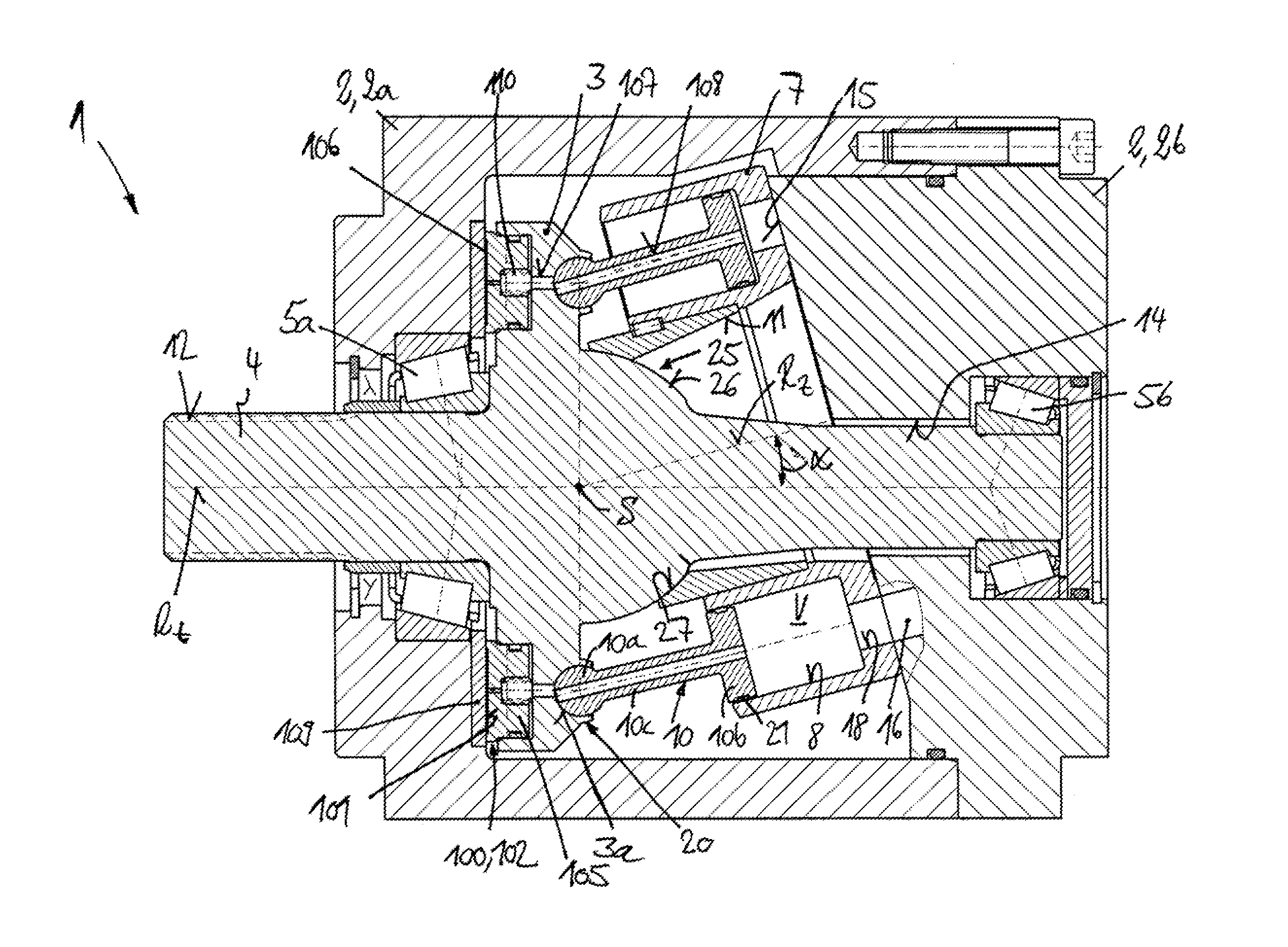
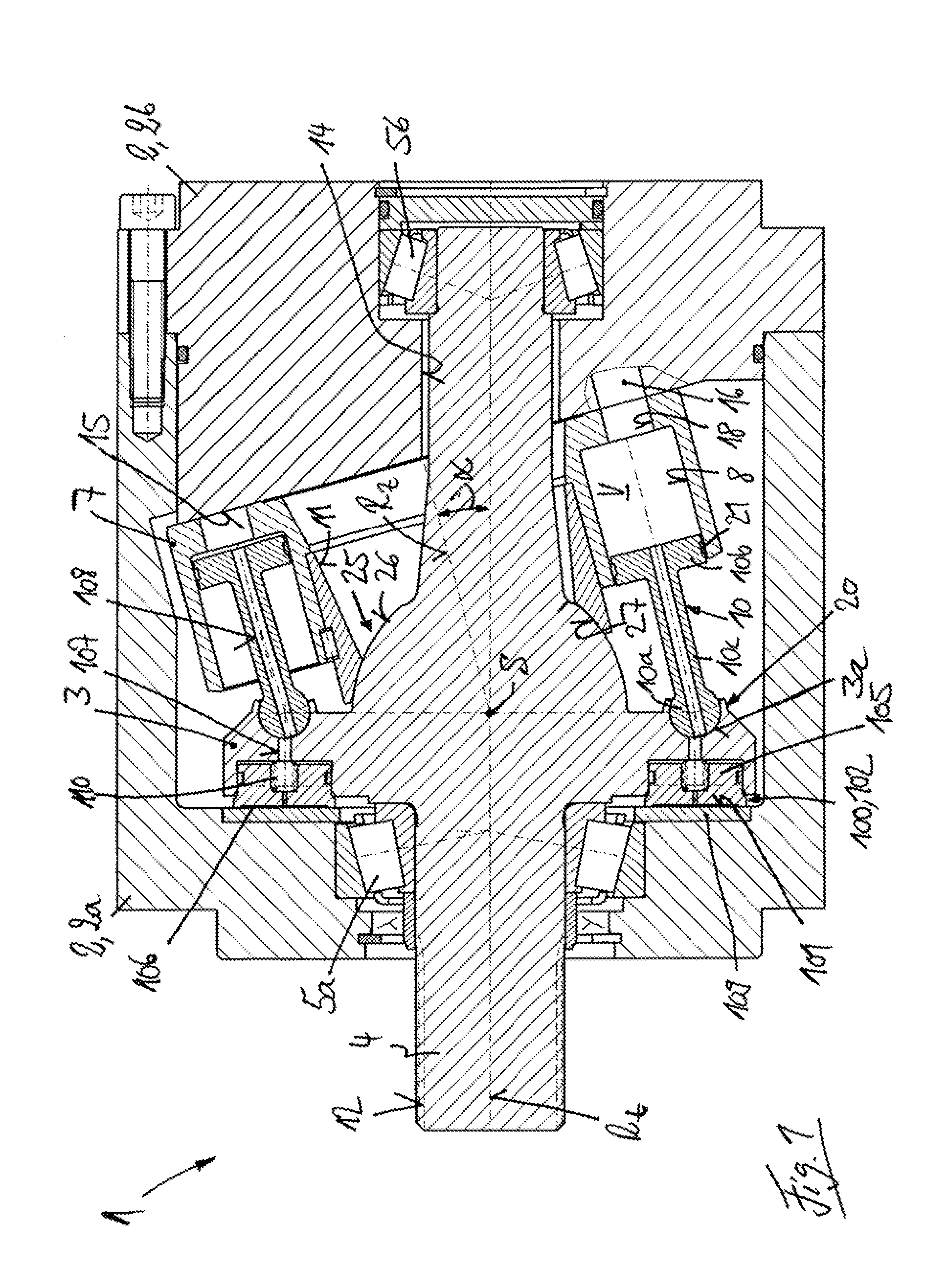
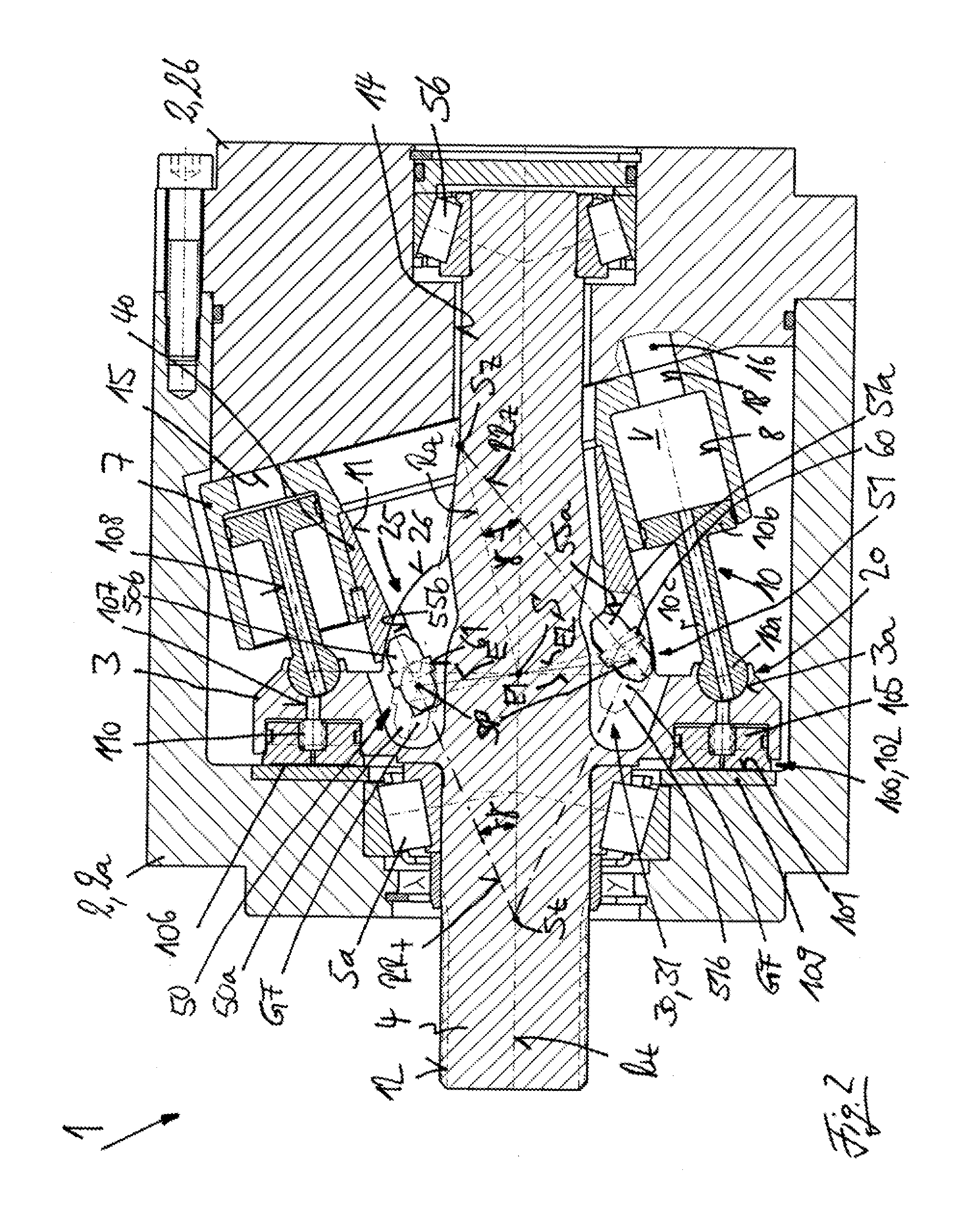
[0047]A hydrostatic axial piston machine 1 in the form of a band-axis machine is illustrated in FIGS. 1 and 2. The machine 1 has a housing 2 that includes a housing barrel 2a and a housing cover 2b fastened to the housing barrel 2a. A driveshaft 4 provided with a drive flange 3 is mounted in the housing 2 by bearing devices 5a, 5b so that it can rotate around an axis of rotation Rt. In the illustrated exemplary embodiment, the drive flange 3 is formed in one piece with the driveshaft 4, so that the driveshaft 4 and the drive flange 3 can be manufactured as a single part.

[0048]Located in the housing 2 axially next to the drive flange 3 is a cylinder barrel 7, which is installed so that it can rotate around an axis of rotation RZ and includes a plurality of piston bores 8, which in the illustrated exemplary embodiment are arranged concentrically around the axis of rotation RZ of the cylinder barrel 7. A longitudinally displaceable piston 10 is located in each piston bore 8.

[0049]The a...


PUM


Abstract

A hydrostatic axial piston machine (1) utilizing a bent-axis construction has a driveshaft (4) with a drive flange (3) rotatable around an axis of rotation (Rt) inside a housing (2). A cylinder barrel (7) has pistons (10) fastened in an articulated manner to the drive flange (3). The drive flange (3) is supported on a housing-side slide face (101) by an axial bearing (100) in the form of a hydrostatically relieved sliding bearing (102) having a plurality of slippers (105). Each of the slippers (105) is mounted in an articulated manner in the drive flange (3) so that when the drive flange (3) rotates, a compensating force (FFR) acts on the slipper (105) which is in the opposite direction to the centrifugal force (FF) acting on the slipper (105). The point of application (AP) of the compensating force (FFR) on the slipper (105) is selected so that there is no tipping moment on the slipper (105) or to compensate for some or all of any tipping moment that does occur.

Description

CROSS REFERENCE TO RELATED APPLICATIONS[0001]This application claims priority to German Application No. DE 102014104952.7 filed Apr. 8, 2014, which is herein incorporated by reference in its entirety.BACKGROUND OF THE INVENTION[0002]1. Field of the Invention[0003]This invention relates to a hydrostatic axial piston machine utilizing a bent-axis construction having a driveshaft with a drive flange located inside a housing and rotatable around an axis of rotation. A cylinder barrel is located inside the housing and is rotatable around an axis of rotation. The cylinder barrel includes a plurality of piston bores. A longitudinally displaceable piston is located in each piston bore. The pistons are fastened to the drive flange in an articulated manner. The drive flange is supported on a housing-side slide face by an axial bearing that is in the form of a hydrostatically relieved sliding bearing having a plurality of slippers, each of which is mounted in an articulated manner on the drive...

Claims


Application Information

Patent Timeline
Patent Type & Authority Applications(United States)
IPC IPC(8): F01B3/00
CPCF01B3/0082F01B3/0002F04B1/126F04B1/2071F04B1/2078F04B1/2092F03C1/0665F03C1/0668F03C1/0671F04B1/2085F04C2240/54
Inventor BERGMANN, MARTIN
Owner LINDE HYDRAULICS
Why Eureka
Try Eureka