
Keyboard stand

Active Publication Date: 2015-09-24
U S BAND & ORCHESTRA SUPPLIES INC
View PDF37 Cites 18 Cited by
  • Summary
  • Abstract
  • Description
  • Claims
  • Application Information

AI Technical Summary

Benefits of technology

The invention is a portable and stable stand that allows the user to adjust the height without changing the width between the arms and legs. The stand has interlocking clamps that allow for easy adjustment and tightening, as well as guide pins to prevent locking. The stand is made from a modified I-beam with flexible flanges and a tension knob to secure the arms and legs in place. The stand can accommodate different keyboard sizes and is ideal for transport and storage.

Problems solved by technology

Different stand constructions have been made available in the past, but generally, these are relatively expensive, complicated or cumbersome in construction.
One drawback of X-type stands is that the stability of the stand is compromised as the height of the keyboard or DJ coffin is raised since the lateral distance between the opposing arms and legs decreases as the height increases.
A secondary defect is that at lower positions the width of the arms is too great to be used with smaller keyboards or coffins.
Even though this type of stand is portable, Z-type stands are much less portable than X-type stands.
The disadvantage of this type of stand is its size, especially when folded for storage.
Even when it is collapsed, this type of stand is not very compact.
An additional drawback of the design is difficulty in folding.
The required effort and time to collapse this type of stand is significant.
While these stands fold to a relatively flat form for transport, they, like the Z-type, take a significant amount of effort to get them as small as possible.
C-type stands are the most expensive of all the common stand types.
Disadvantages are that the stand is no more stable than an X-type stand, and often less stable.
The column limits horizontal adjustment of the keyboard and is bulky to transport, being typically 48 inches long.
Some models do not have storage for the arms and legs within the column, while some do.

Method used


Image

  • Keyboard stand
  • Keyboard stand
  • Keyboard stand

Examples


Embodiment Construction

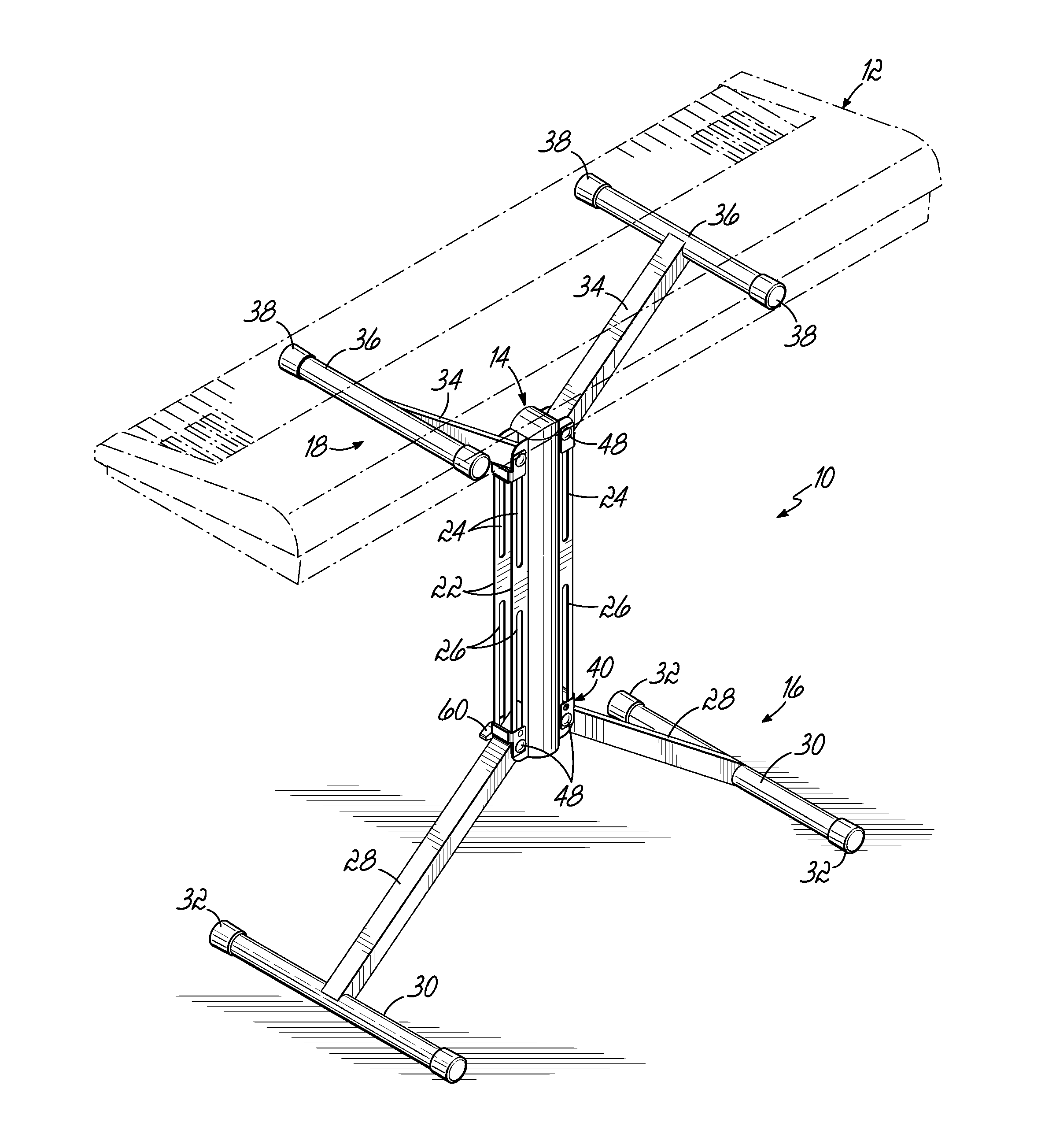
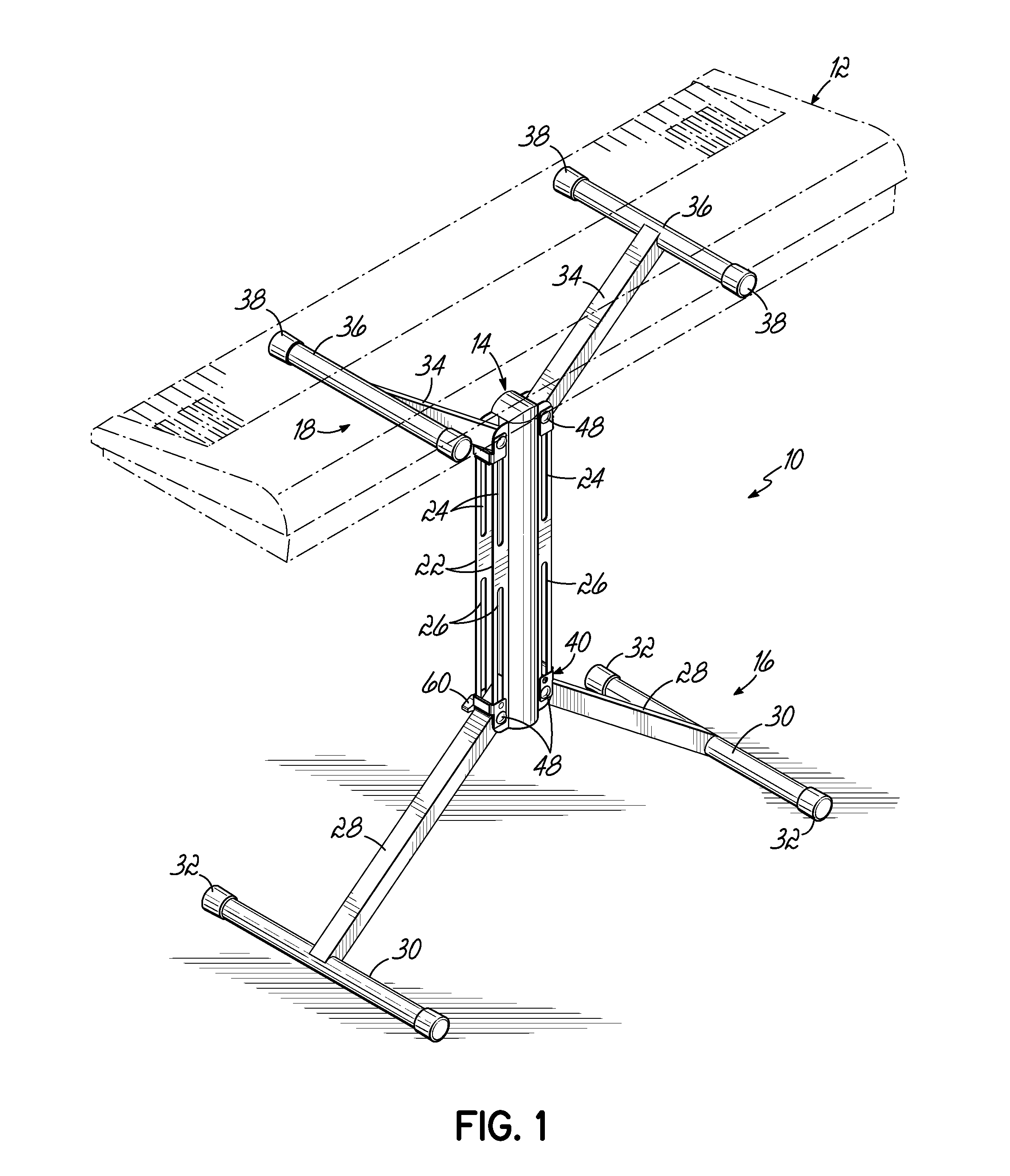
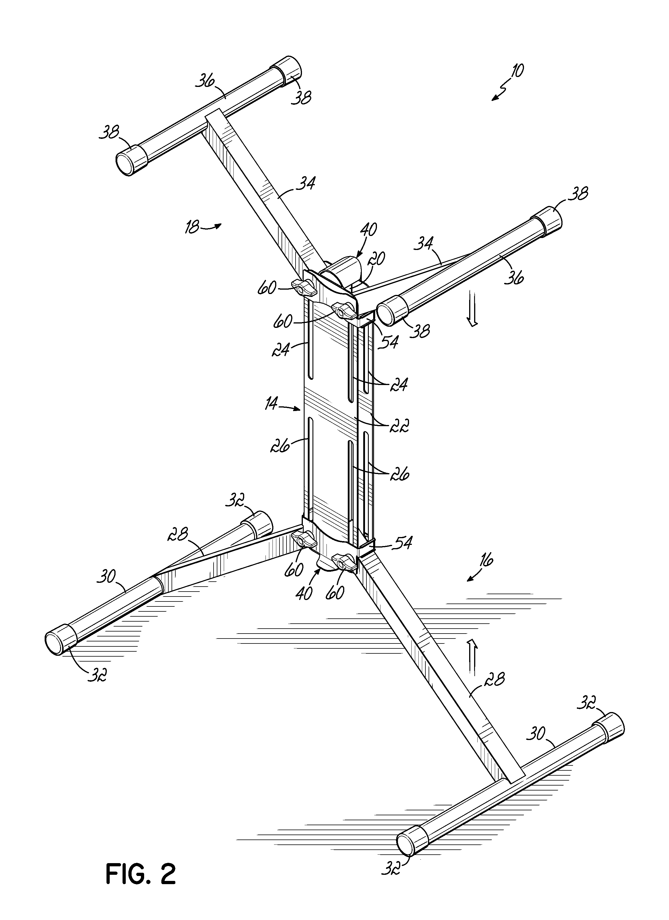
[0037]Referring to FIGS. 1-7C, one embodiment of a stand 10 adapted to support a musical electronic keyboard 12 according to this invention is shown. The invention herein is described for use with a keyboard 12, but any musical item or other work piece may be used on the stand 10. The stand 10 includes a central, generally vertically extending member or column 14. Coupled to a lower portion of the column 14 is a leg assembly 16 adapted to support the stand 10 on a floor surface or the like. An arm assembly 18 is coupled to the upper portion of the column 14. The column 14 includes a central post 20 which, in various embodiments, has two pairs of flanges 22 extending on opposite lateral sides of the post 20. Each flange 22 has an upper and a lower slot 24, 26 generally vertically oriented. The leg assembly 16 includes a pair of oppositely extending legs 28. A foot 30 extends perpendicularly to the longitudinal axis of each leg 28 at a distal end of each leg and may include a rubber f...


PUM


Abstract

A stand for a musical keyboard is both stable in a deployed configuration and conveniently compact and portable in a collapsed configuration. The separation of the arms and legs may not change in width as the height of the stand is adjusted. The stand has two “floating” V's, one for the arms and one for the legs. These components slide vertically in slots in a central column and are locked in place with clamps that wrap around the column. To adjust the height of the stand, a user loosens either or both the top and / or bottom clamp (arm clamp or leg clamp) and slides the associated floating V up or down along the center column, then re-tightening the clamp when adjustments are finished. For transport and storage, the user loosens each clamp and rotates the arms or legs in, towards the column.

Description

[0001]This claims the benefit of U.S. Provisional Patent Application Ser. No. 61 / 968,420, filed Mar. 21, 2014 and hereby incorporated by reference in its entirety.BACKGROUND OF THE INVENTION[0002]This invention relates to a stand for supporting electronic piano type keyboard boxes, commonly referred to as keyboards, and cased equipment used by disc jockeys or DJ's (commonly referred to as DJ coffins) in different vertical positions in a horizontal orientation to facilitate a variety of users operating the keyboard from either a standing or sitting position.[0003]The desire to support items has been known in some industries for many years. In a basic form, the concept may involve a readily deployable and collapsible support stand that is able to accommodate and support anticipated loads. In general, an electronic instrument type of keyboard and DJ coffins comprise a relatively long, narrow and low box-like configuration. The keyboards and coffins are portable and generally are moved ...

Claims


Application Information

Patent Timeline
IPC IPC(8): F16M11/24G10C3/12
CPCF16M11/24G10C3/12F16M11/242F16M11/247G10G5/00G10H1/32F16M11/32F16M11/38
Inventor CARPENTER, WILLIAM M.
Owner U S BAND & ORCHESTRA SUPPLIES INC
Learn More