
Transmission Gear, Roller Reducer Comprising the Transmission Gear, and Method of Assembly Thereof

Active Publication Date: 2015-09-24
DIAKONT ADVANCED TECH
View PDF4 Cites 9 Cited by
  • Summary
  • Abstract
  • Description
  • Claims
  • Application Information

AI Technical Summary

Benefits of technology

This patent is about a new roller reducer for gear mechanisms. The inventive gear mechanism includes flange rings that help to eliminate bending of the rollers and shaft, which can lead to reduced efficiency and wear. The flange rings help to distribute load in a radial direction, which reduces damage to the thread interfaces and increases the efficiency and service life of the reducer. The reducer operates more efficiently with no extra elements, and can provide high gear ratios. The patent also includes a method for mounting the rollers onto the shaft with engagement between the roller and shaft threads. Overall, this new roller reducer provides greater efficiency and durability.

Problems solved by technology

A disadvantage of SU 1294606 is that the rollers tend to bend in the central or proximal part thereof along the shaft upon transmitting high torque, which leads to a shift of contact points towards thread edge and to edge contact, leading to a decreased load-bearing capacity of the reducer, greater slip and worse efficiency.
Further, SU 1294606 disadvantageously prevents from providing a play-free transmission because pressing together nuts of each of the members, to allegedly eliminate play in thread interfaces, can cause slip of the rollers, and the play will persist.

Method used


Image

  • Transmission Gear, Roller Reducer Comprising the Transmission Gear, and Method of Assembly Thereof
  • Transmission Gear, Roller Reducer Comprising the Transmission Gear, and Method of Assembly Thereof
  • Transmission Gear, Roller Reducer Comprising the Transmission Gear, and Method of Assembly Thereof

Examples


Embodiment Construction

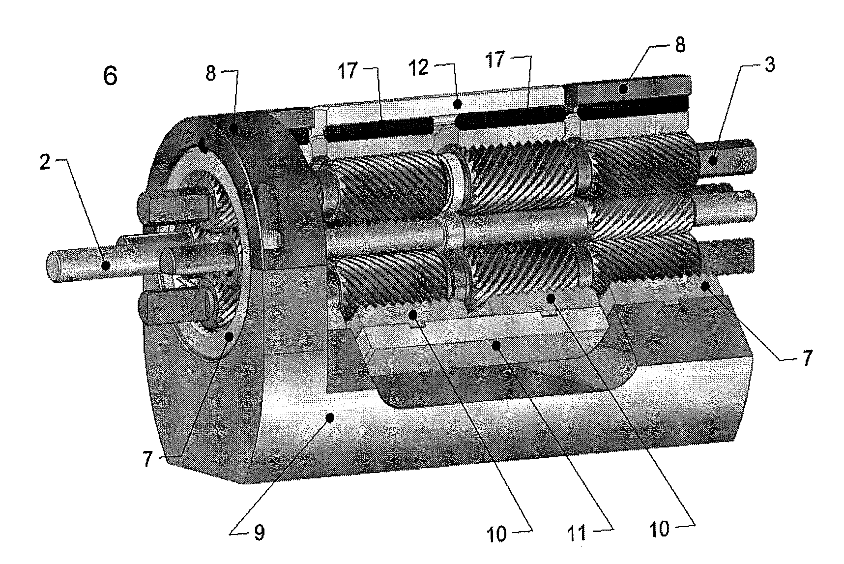
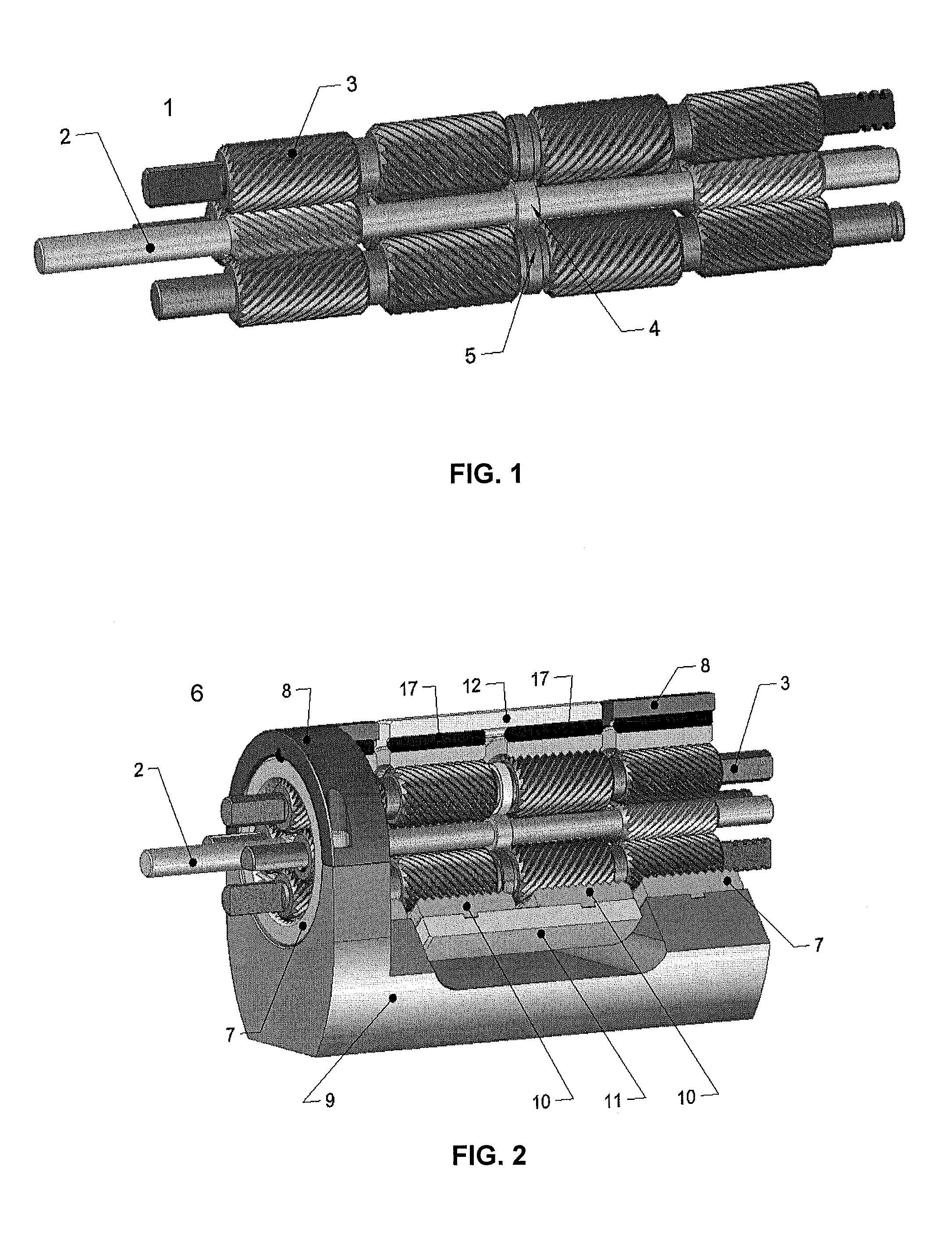
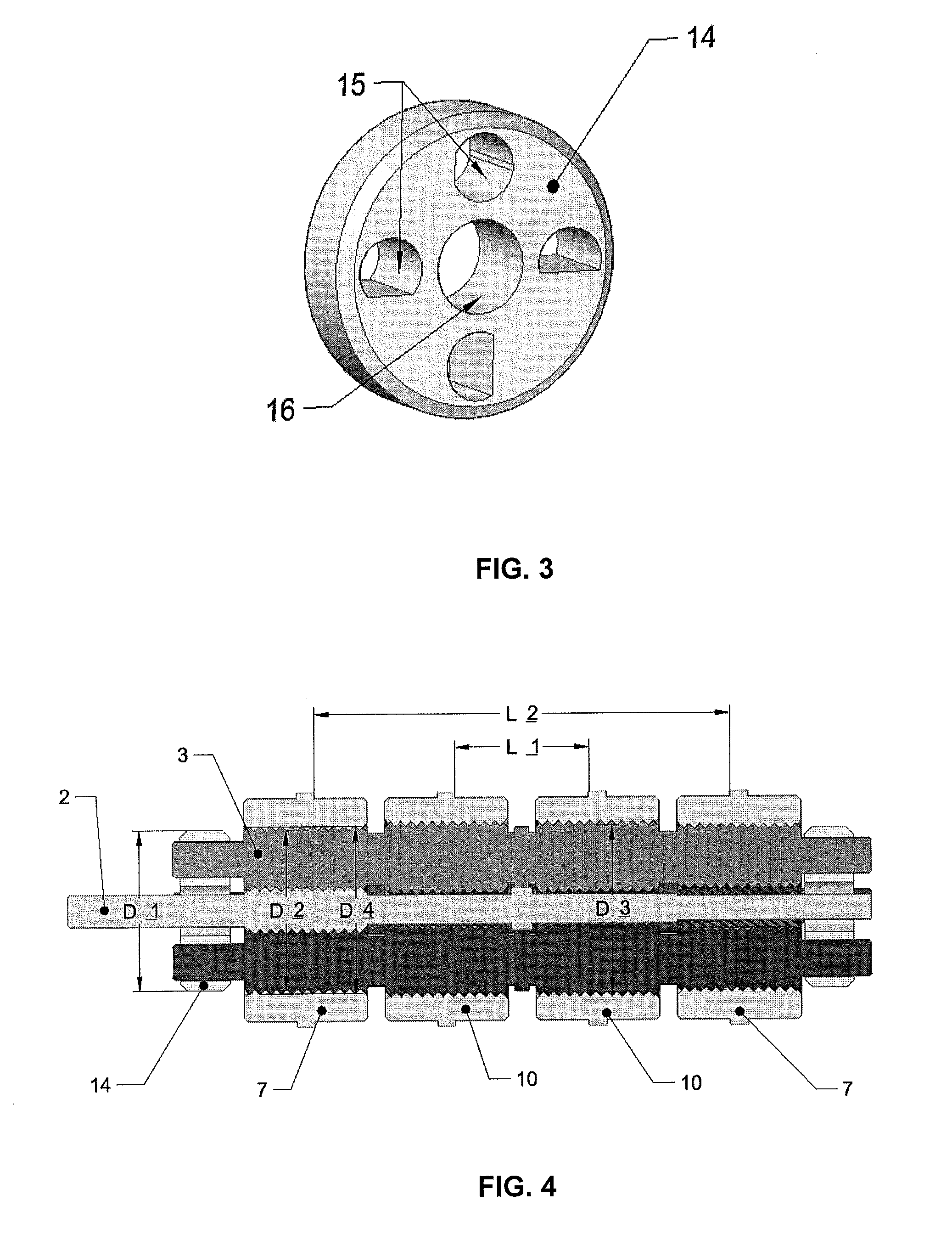
[0059]According to one embodiment shown in FIG. 1, transmission gear 1 comprises an externally threaded shaft 2 and four rollers 3 arranged around the shaft 2.

[0060]The shaft 2 serves as an input high-velocity member of the transmission gear 1. As shown in FIG. 1, the shaft 2 comprises a left-handed thread portion and a right-handed thread portion. The portions have threads of the same diameter. The thread portions are arranged distally at distal sections of the shaft. In other embodiments, however, these thread portions can be arranged proximally in the center of the shaft 2. In further embodiments, the shaft 2 can comprise more than two thread portions.

[0061]In one embodiment shown in FIG. 1, the shaft 2 comprises a flange ring 4 arranged in the central part thereof. In other embodiments, however, e.g. when the shaft thread portions are arranged in the center of the shaft, the shaft can comprise at least two flange rings arranged at distal sections thereof. Diameter of the flange ...


PUM

PropertyMeasurementUnit
Timeaaaaaaaaaa
Fractionaaaaaaaaaa
Diameteraaaaaaaaaa

Abstract

The present invention relates to a roller reducer comprising a transmission gear having an externally threaded shaft having at least one left-handed thread portion, at least one right-handed thread portion, and at least one shaft flange ring, and a plurality of rollers, each roller having a plurality of thread portions, comprising at least one left-handed thread portion and at least one right-handed thread portion, each thread portion arranged to engage with the respective thread portions of the shaft, and at least one roller flange ring arranged adjacent to the roller thread portions to rotationally slide against the corresponding at least one flange ring of the shaft.Diameters of the flange rings of the rollers and the flange rings of the shaft are each equal to the respective effective thread diameters of the engaged thread portions of the rollers and the shaft, respectively.

Description

FIELD OF THE INVENTION[0001]The present invention relates to planetary gears for transmitting rotational movement, in particular to planetary gear reducers with stepped threaded rollers.BACKGROUND OF THE INVENTION[0002]Roller reducers are a subset of planetary reducers and can be used for adjusting torque and as a rotation / linear motion converters. In particular, roller reducers can be used in robots, manipulators and power drives requiring transmission of large amounts of torque under size restrictions. Such reducers have the following advantages: simple design and few components; high kinematic accuracy provided by a short kinematic chain and many contact points; smooth and low-noise operation; small dimensions while providing high transmitted torque; and operation at high input shaft rotation velocities.[0003]Inventor's Certificate SU 1294606 discloses a manipulator joint formed by a roller reducer; the joint comprises a threaded shaft and threaded rollers forming a planetary gea...

Claims


Application Information

Patent Timeline
IPC IPC(8): F16H1/28F16H57/08F16H57/023F16H57/021
CPCF16H1/2863F16H57/023F16H57/08F16H57/021F16H25/2252Y10T29/49465F16H1/28F16H25/00
Inventor FEDOSOVSKY, MIKHAIL EVGENIEVICHDUNAEV, VADIM IGOREVICHPUSTOZEROV, ROMAN VLADIMIROVICHANSPUK, DMITRIY ADAMOVICH
Owner DIAKONT ADVANCED TECH
Learn More