
System and Method for Chromatic Dispersion Tolerant Direct Optical Detection

a technology of direct optical detection and chromatic dispersion, applied in the field of optical communication, can solve the problems of frequency-dependent fading, optical modulator operation, non-ideal ssb signal,

Inactive Publication Date: 2015-09-10
HUAWEI TECH CO LTD
View PDF4 Cites 7 Cited by
  • Summary
  • Abstract
  • Description
  • Claims
  • Application Information

AI Technical Summary

Benefits of technology

The invention is a method and system for direct detection optical transmission using a nonlinear equalizer. The method involves adjusting the drive voltage for the optical modulator based on a mapping between the drive voltage and the output of the optical modulator, which is an inverse function of the nonlinear transfer function. The adjusted drive voltage is then used to drive the output of the optical modulator, resulting in a single-side band signal that is sufficiently linear with respect to the drive voltage for direct detection at the receiver. The technical effects of the invention include improved transmission quality and increased efficiency in optical communication systems.

Problems solved by technology

Chromatic dispersion (CD) can result in frequency-dependent fading for double-side band (DSB) optical signal transmission when a direct detection receiver type is used.
However, the presence of the DC bias causes the optical modulator to operate in a nonlinear region of its transfer function.
This produces a non-ideal SSB signal and its transmission becomes no longer immune to the CD induced fading effect.
Hence, the detection performance is severely degraded.

Method used


Image

  • System and Method for Chromatic Dispersion Tolerant Direct Optical Detection
  • System and Method for Chromatic Dispersion Tolerant Direct Optical Detection
  • System and Method for Chromatic Dispersion Tolerant Direct Optical Detection

Examples


Embodiment Construction

[0018]The making and using of the presently preferred embodiments are discussed in detail below. It should be appreciated, however, that the present invention provides many applicable inventive concepts that can be embodied in a wide variety of specific contexts. The specific embodiments discussed are merely illustrative of specific ways to make and use the invention, and do not limit the scope of the invention.

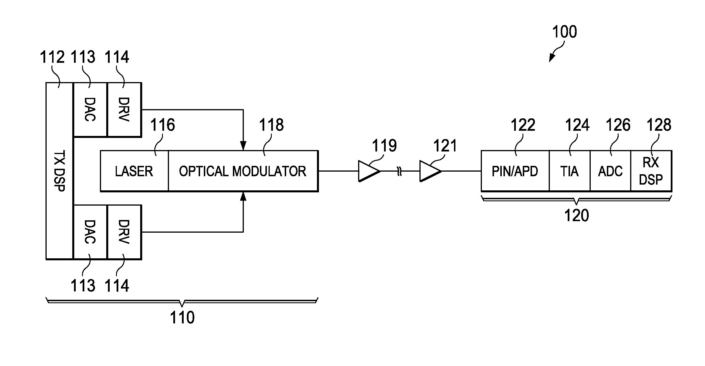
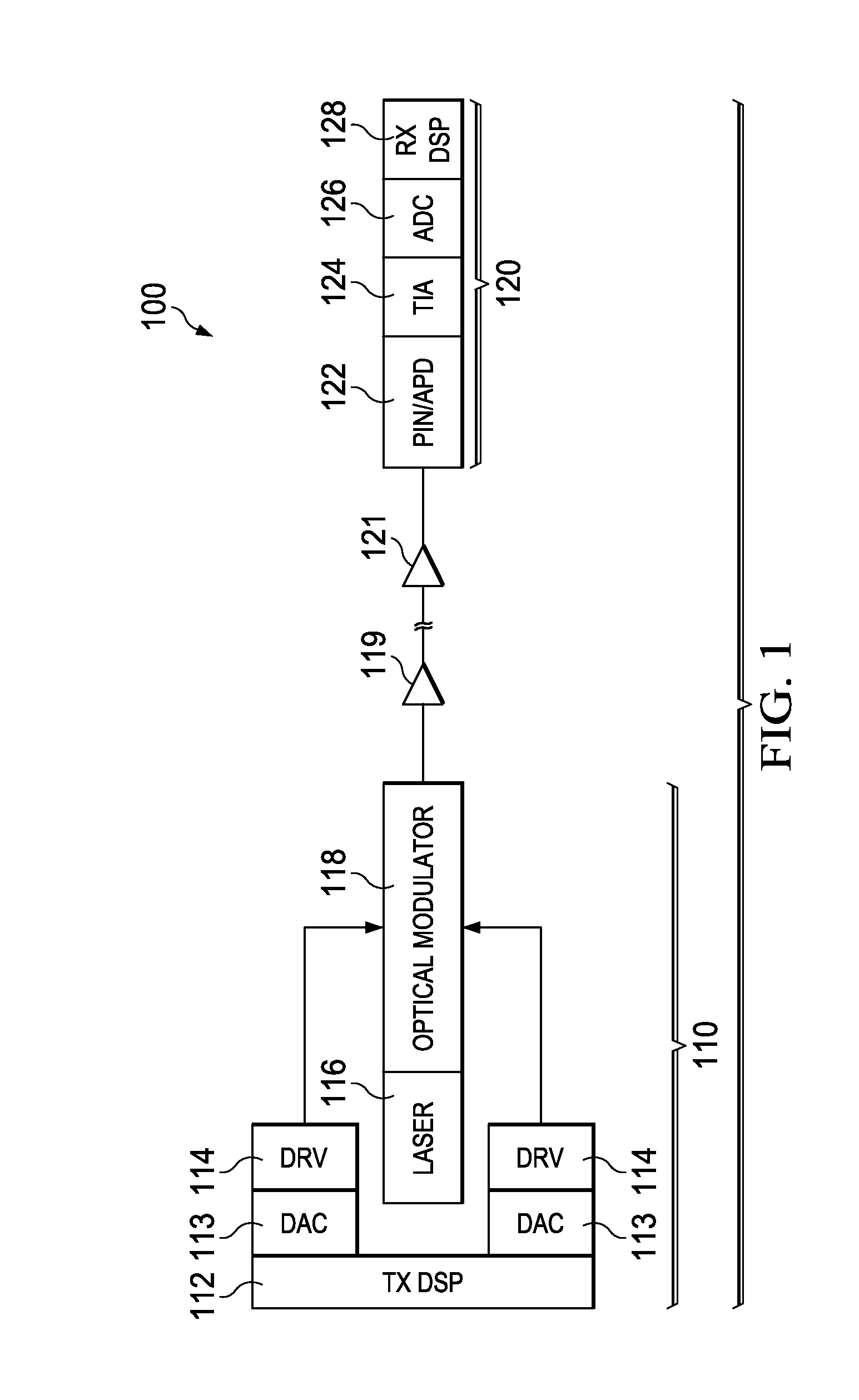
[0019]FIG. 1 shows an example of an optical orthogonal frequency-division multiplexing (OFDM) transmission system 100 that enables direct detection. The system 200 includes a transmitter 110 and a direct detection receiver 120, which are linked via an optical fiber. The transmitter 110 comprises a laser 116, an optical modulator 118 coupled to the output of the laser 116 to modulate the optical signals from the laser 116, and an optical amplifier 119 in front of the optical modulator 118. The optical modulator 118 is based on a Mach-Zehnder (MZ) interferometer design driven e...


PUM


Abstract

Embodiments are provided to improve direct detection for optical transmissions. In an embodiment, a method by a transmitter includes adjusting, using a nonlinear equalizer (NLE), a drive voltage for an optical modulator in accordance with a mapping between the drive voltage and an output of the optical modulator. The mapping is an inverse function of a nonlinear transfer function at the optical modulator between the output and to the drive voltage. The method further includes driving, using the adjusted drive voltage, the output of the optical modulator. The output is a single-side band (SSB) signal and is sufficiently linear with respect to the drive voltage for allowing direct detection at a receiver.

Description

TECHNICAL FIELD[0001]The present invention relates to the field of optical communications, and, in particular embodiments, to a system and method for chromatic dispersion tolerant direct optical detection.BACKGROUND[0002]Chromatic dispersion (CD) can result in frequency-dependent fading for double-side band (DSB) optical signal transmission when a direct detection receiver type is used. This fading effect can be circumvented by transmitting a single-side band (SSB) signal generated via digital signal processing (DSP). The SSB causes orthogonal frequency-division multiplexing (OFDM) subcarriers after direct detection to experience a frequency-dependent phase shift without CD. The frequency-dependent phase shift can then be compensated using a one-tap linear equalizer. To facilitate direct detection, the optical carrier is transmitted along with the SSB signal over the optical fiber. One method to generate this optical carrier is to use a DC bias voltage at the optical modulator at th...

Claims


Application Information

Patent Timeline
IPC IPC(8): H04B10/564H04B10/516
CPCH04B10/516H04B10/564H04B10/25137H04B10/588
Inventor CHEN, CHENLI, CHUANDONGZHANG, ZHUHONG
Owner HUAWEI TECH CO LTD
Learn More