
Tunable Resonances from Conductively Coupled Plasmonic Nanorods

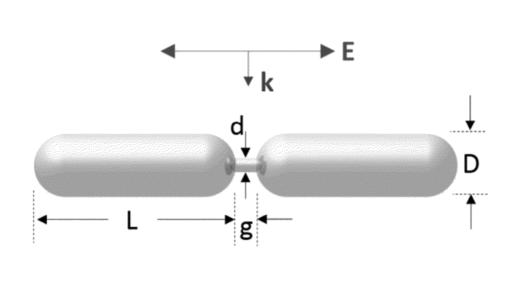
a plasmonic nanorod and conductively coupled technology, applied in the direction of instruments, material analysis, polarisation-affecting properties, etc., can solve the problems of limiting the availability of nanostructures that resonate at desired wavelengths, synthesis of high-aspect ratio (high-ar) nanoparticles, and proving difficul

Inactive Publication Date: 2015-09-03
THE UNITED STATES OF AMERICA AS REPRESENTED BY THE SECRETARY OF THE NAVY
View PDF0 Cites 14 Cited by
  • Summary
  • Abstract
  • Description
  • Claims
  • Application Information

AI Technical Summary

Benefits of technology

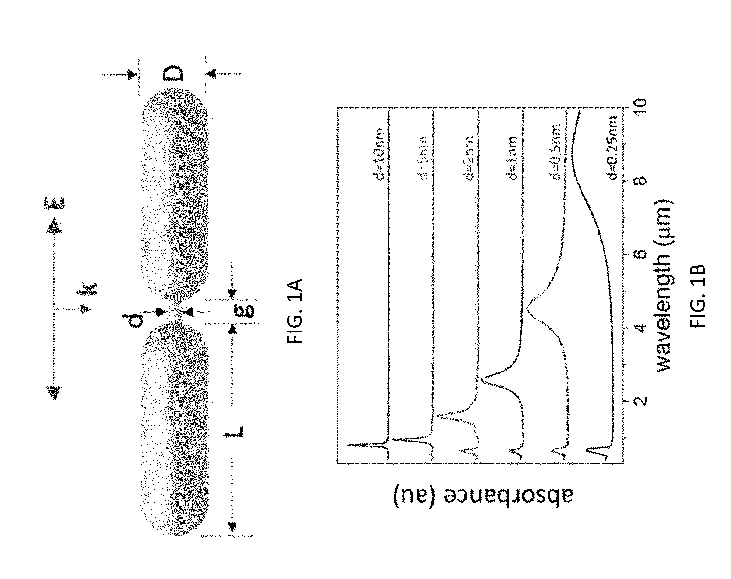
The patent text describes a new type of nanostructure that can be used for imaging and therapy. This structure has two plasmonic nanorods that are connected by a conductive junction. The resonant wavelength of this structure can be controlled by adjusting the gap between the nanorods. This allows for better imaging and therapy of cells, tissues, and organs.

Problems solved by technology

Synthesis of high aspect ratio (high-AR) nanoparticles, i.e., those that are significantly longer than wide, has proven difficult.
This limits availability of such nanostructures that resonate at desired wavelengths.

Method used


Image

  • Tunable Resonances from Conductively Coupled Plasmonic Nanorods
  • Tunable Resonances from Conductively Coupled Plasmonic Nanorods
  • Tunable Resonances from Conductively Coupled Plasmonic Nanorods

Examples


Embodiment Construction

Definitions

[0011]Before describing the present invention in detail, it is to be understood that the terminology used in the specification is for the purpose of describing particular embodiments, and is not necessarily intended to be limiting. Although many methods, structures and materials similar, modified, or equivalent to those described herein can be used in the practice of the present invention without undue experimentation, the preferred methods, structures and materials are described herein. In describing and claiming the present invention, the following terminology will be used in accordance with the definitions set out below.

[0012]As used in this specification and the appended claims, the singular forms “a”, “an,” and “the” do not preclude plural referents, unless the content clearly dictates otherwise.

[0013]As used herein, the term “and / or” includes any and all combinations of one or more of the associated listed items.

[0014]As used herein, the term “about” when used in co...


PUM


Abstract

A plasmonic nanostructure includes two plasmonic nanorods spaced apart by a gap and interconnected by a conductive junction spanning the gap, and mimics a longer nanostructure. This provides an ability to tune a structure in wavelengths that would be difficult to otherwise achieve.

Description

BACKGROUND[0001]Synthesis of high aspect ratio (high-AR) nanoparticles, i.e., those that are significantly longer than wide, has proven difficult. This limits availability of such nanostructures that resonate at desired wavelengths. A need exists to surmount this problem.BRIEF SUMMARY[0002]In a first embodiment, a sub-wavelength plasmonic nanostructure includes two plasmonic nanorods spaced apart by a gap and interconnected by a conductive junction spanning the gap.[0003]A further embodiment, a method of using a plasmonic nanostructure includes providing a plasmonic nanostructure according to the first embodiment, introducing the plasmonic nanostructure to a cell, tissue, or organism, and then subjecting the cell, tissue, or organism to imaging and / or photothermal therapy.[0004]In another embodiment, a method of tuning a sub-wavelength plasmonic nanostructure includes identifying a need for a nanostructure with a resonant wavelength of x; and providing a plasmonic nanostructure acco...

Claims


Application Information

Patent Timeline
IPC IPC(8): G01N21/65
CPCG01N21/658B82Y20/00Y10S977/811Y10S977/81G01N21/21G01N21/554G01N2021/217
Inventor FONTANA, JAKERATNA, BANAHALLI R.
Owner THE UNITED STATES OF AMERICA AS REPRESENTED BY THE SECRETARY OF THE NAVY
Learn More