Two-Dimensional Model of Triangular Sectors for Use in Generating a Mesh for Finite Element Analysis

a two-dimensional model and finite element technology, applied in the field offinite element analysis, can solve the problems of inability to generate a mesh for an object, affecting the accuracy of mesh generation, and increasing the difficulty of performing shear load calculations,

Active Publication Date: 2015-08-27
THE BOEING CO
View PDF4 Cites 12 Cited by
  • Summary
  • Abstract
  • Description
  • Claims
  • Application Information

AI Technical Summary

Benefits of technology

The patent describes an apparatus and method for analyzing joints in structures using triangles. The apparatus creates a first graph based on points in a region where fastener devices will be installed, identifies primary and secondary points on the first graph, and creates a second graph using the first graph and the primary and secondary points. The second graph is used to generate a two-dimensional model made up of triangles that can be used for finite element analysis of the joint. The analysis results are used to control design, manufacturing, or maintenance of the joint. The technical effect is improved accuracy and efficiency in analyzing joints in structures using triangles.

Problems solved by technology

As the number of bolts that form the bolted joint increases, performing shear load calculations may become more and more difficult.
In some cases, these mesh generation techniques may be unable to generate a mesh for an object when the geometry of the object is too irregular or complex.
When a mesh is irregular, making modifications to the mesh may be more difficult than desired.
These small design changes may result in corresponding changes in a portion of the geometry of the object.
Depending on the level of irregularity of the geometry of the object, some currently available mesh generation techniques may be unable to modify the corresponding portion of the mesh based on the changes in the portion of the geometry of the object.
Generating a new mesh may require more time and processing resources than desired, which may lead to a reduced efficiency in the analysis of the object.
This reduced efficiency may, in turn, lead to delays in the overall manufacturing of the object.

Method used


Image

  • Two-Dimensional Model of Triangular Sectors for Use in Generating a Mesh for Finite Element Analysis
  • Two-Dimensional Model of Triangular Sectors for Use in Generating a Mesh for Finite Element Analysis
  • Two-Dimensional Model of Triangular Sectors for Use in Generating a Mesh for Finite Element Analysis

Examples


Embodiment Construction

[0051]The illustrative embodiments recognize and take into account different considerations. For example, the illustrative embodiments recognize and take into account that it may be desirable to have a method for generating a mesh for an object in which the mesh is easily modifiable and easily repeatable. More particularly, the illustrative embodiments recognize and take into account that it may be desirable to have a method for generating a mesh for a bolted joint having irregular geometry with the same level of ease and accuracy as a bolted joint that has regular geometry.

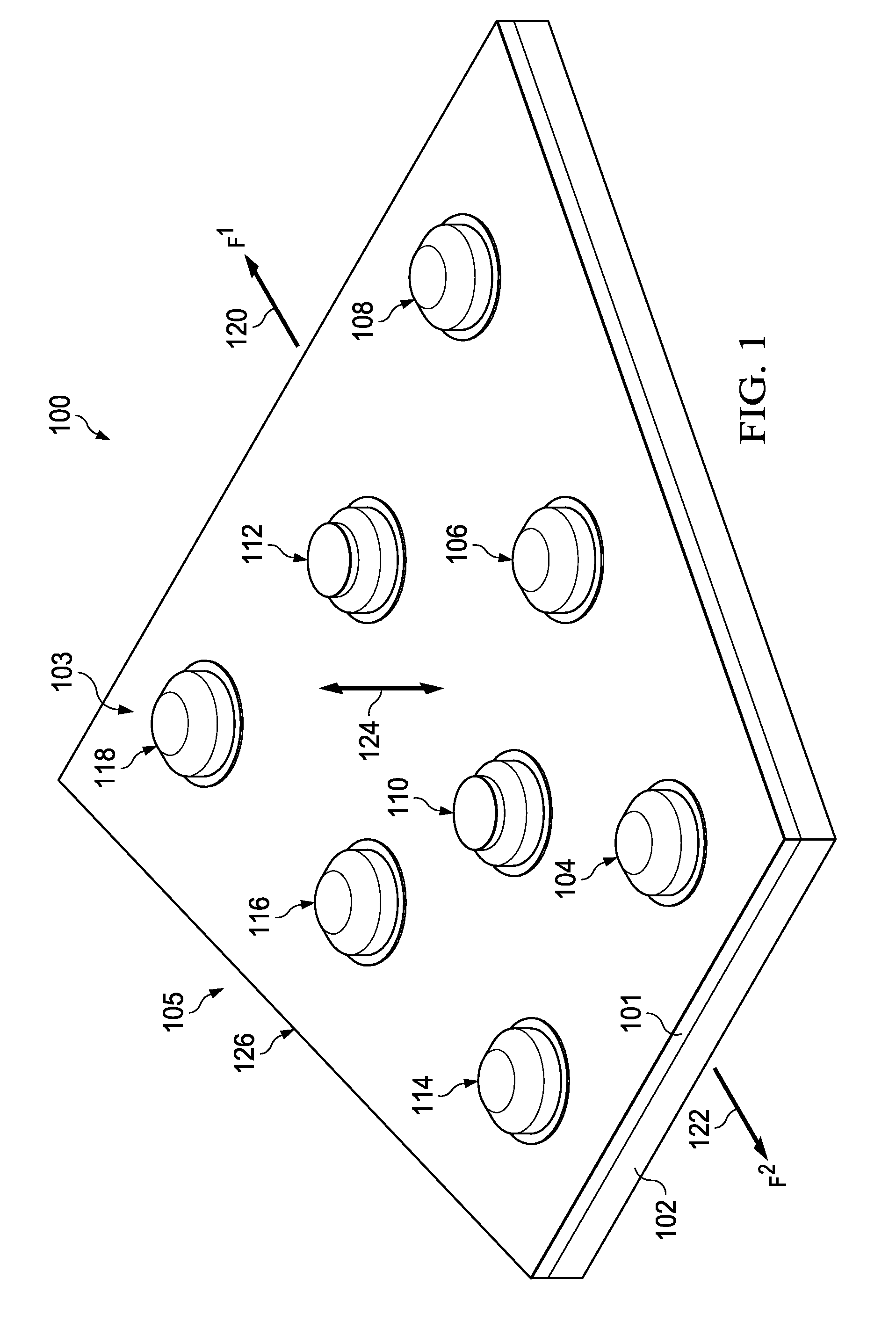
[0052]Referring now to the figures and, in particular, with reference to FIG. 1, an illustration of a bolted joint having irregular geometry is depicted in accordance with an illustrative embodiment. Bolted joint 100 is an example of a joint that may be manufactured based on the analysis provided by a finite element analysis system, such as finite element analysis system described below in FIG. 2.

[0053]In this il...


PUM


Abstract

A method and apparatus for analyzing a joint. The apparatus comprises a graph generator and a model generator. The graph generator forms a first graph based on a plurality of points within a region. The plurality of points represent a plurality of locations relative to a structure for a plurality of fastener devices configured to be installed in the structure to form a joint. The graph generator is configured to identify primary points and secondary points based on the first graph. The graph generator is further configured to form a second graph using the primary points, the secondary points, and the first graph. The model generator is configured to generate a two-dimensional model comprised of triangular sectors using vertices of the second graph. The two-dimensional model is configured for use in forming a mesh for use in performing finite element analysis for the joint.

Description

BACKGROUND INFORMATION[0001]1. Field[0002]The present disclosure relates generally to finite element analysis and, in particular, to generating a mesh for use in performing finite element analysis. Still more particularly, the present disclosure relates to a method and apparatus for generating a two-dimensional model comprised of triangular sectors for use in generating the mesh for the finite element analysis.[0003]2. Background[0004]Bolts are oftentimes used to secure various types of structures together. A bolted joint is formed when at least one bolt and nut are used to join at least two structures together. A bolted joint may include any number of structures that are joined together using any number of bolts. In some cases, it may be desirable to calculate the shear load carried by each bolt in the bolted joint. For example, the shear load carried by a particular bolt in a bolted joint may need to be calculated to determine whether the bolt will need to be replaced after some p...

Claims


Application Information

Patent Timeline
IPC IPC(8): G06T17/20
CPCG06T17/20G06F30/23
Inventor GRIP, ROBERT ERIK
Owner THE BOEING CO
Why Eureka
Try Eureka