Support for mounting an accessory to a weapon

a technology for mounting accessories and weapons, which is applied to machine supports, building scaffolds, domestic objects, etc., can solve the problems of unstable position of locking pieces relative to brackets, deterioration of weapon accuracy, and high cost of sniperscopes, etc., and achieves convenient and quick release and mounting, simple and compact design, and the effect of quick us

Inactive Publication Date: 2015-08-27
MASINA TUOTE
View PDF14 Cites 7 Cited by
  • Summary
  • Abstract
  • Description
  • Claims
  • Application Information

AI Technical Summary

Benefits of technology

[0006]The object of the invention is to provide a novel support for mounting an accessory to a weapon, the support having a simpler and more compact design than before and enabling easier and quicker release and mounting than heretofore. The characteristic features of this invention become apparent from the appended claims. The support can be quickly used with one grip without tools. Thus, the accessory can be mounted and released quickly and reliably without tools. During the reinstallation, the position of the bracket remains unaltered, and the bracket can thus be used even for mounting high-magnification sighting devices without deterioration of accuracy. In addition, the locking piece remains in the locked position reliably and the locking is clearance-free and strong.

Problems solved by technology

Sniperscopes, in particular, are expensive and susceptible to damage, such as dents, during storage and transportation.
In this case, the accuracy of the weapon deteriorates after the sighting device has been installed.
In prior art brackets, the position of the locking piece relative to the bracket is unstable.
Thus, the mounting of the bracket is unreliable.
Correspondingly, different mounting devices of the bracket include several different components, which makes the design of a prior art bracket complicated.
In addition, the removal and mounting of the bracket is time-consuming and generally requires tools.
The bracket and particularly the mounting devices also include protruding parts, which increase the risk of damage and accidents and can lead to an inadvertent release of the locking piece from the locked position.
Sighting devices in particular are sensitive.
Thus, even a small clearance or a change in the bracket position spoils the accuracy of the weapon.

Method used


Image

  • Support for mounting an accessory to a weapon
  • Support for mounting an accessory to a weapon
  • Support for mounting an accessory to a weapon

Examples


Embodiment Construction

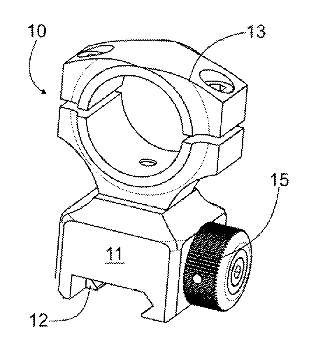
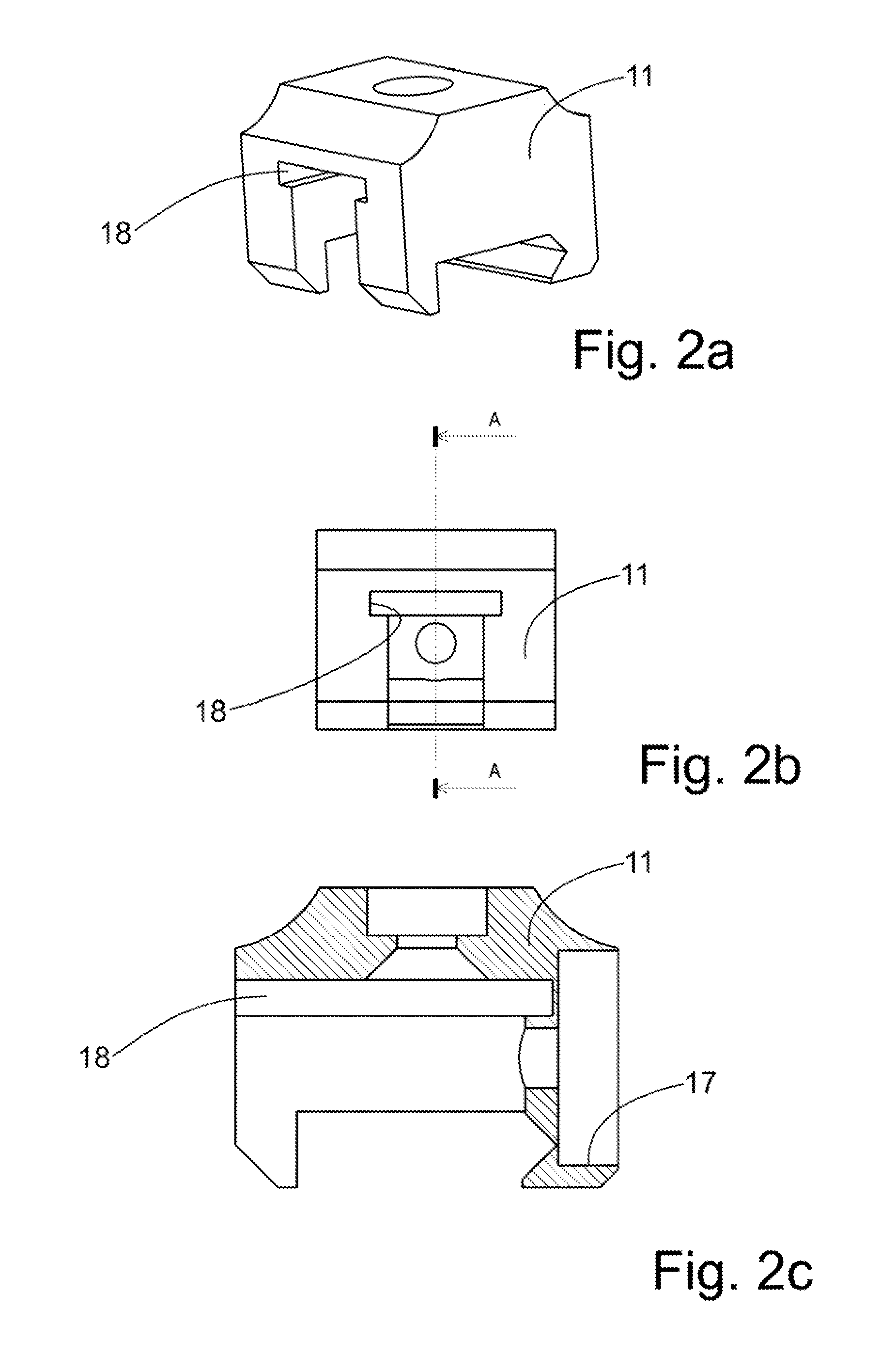
[0036]FIGS. 1a to 1d illustrate a support 10 for mounting a sniperscope, for example. Generally, the support can be used to mount almost any accessory to a weapon, more precisely, to a rail arranged in the weapon. The rail may be separately mounted to the weapon or the rail is formed as a part of a breech carrier, for example (not shown). The support 10 includes a bracket 11 and a locking piece 12. In FIGS. 1a to 1d, a ring 13 for a sniperscope is additionally connected to the bracket 11 with a screw. Two supports, more precisely, two separate brackets with rings, are usually needed to mount one sniperscope. Instead of a ring, another accessory can be mounted to the bracket. According to the invention, the support 10 further includes spring elements 14 for forcing the locking piece 12 fitted in the bracket 11 to a locked position. In other words, the support 10 includes spring elements 14, arranged to act on the locking piece 12, the work direction W of said elements being parallel ...


PUM


Abstract

The invention relates to a support for mounting an accessory to a weapon. The support includes a bracket and a locking piece fitted in the bracket. The support further includes spring elements, arranged to act on the locking piece, the work direction (W) of the elements being parallel to the locking direction (L) of the locking piece arranged in the bracket.

Description

TECHNICAL FIELD[0001]This invention relates to a support for mounting an accessory to a weapon, the support including a bracket and a locking piece fitted to the bracket.BACKGROUND OF THE INVENTION[0002]Various weapons, particularly rifles, are used for different purposes. The selection of a weapon is influenced, for example, by the game animal to be shot and the hunting conditions. Weapons are also used in competitions, such as so-called practical shooting. Particularly sighting devices, such as sniperscopes, exist for various purposes. Thus, when shooting different game animals, one person often has several weapons, which have different sighting devices for different game animals. Sniperscopes, in particular, are expensive and susceptible to damage, such as dents, during storage and transportation. The alignment of sighting devices relative to the weapon may also change. In this case, the accuracy of the weapon deteriorates after the sighting device has been installed.[0003]Today,...

Claims


Application Information

Patent Timeline
Patent Type & Authority Applications(United States)
IPC IPC(8): F41G11/00F16B2/12
CPCF16B2/12F41G11/004F41G11/003F41C27/00F41G1/387
Inventor SILVENNOINEN, MARTTI
Owner MASINA TUOTE
Why Eureka
Try Eureka