Multi-tool adaptor

a multi-tool and adaptor technology, applied in the field of multi-tools and adaptors, can solve the problems of limited overall functioning of multi-tools and/or punch presses

Active Publication Date: 2015-08-27
WILSON TOOL INT
View PDF6 Cites 7 Cited by
  • Summary
  • Abstract
  • Description
  • Claims
  • Application Information

AI Technical Summary

Benefits of technology

[0007]In certain embodiments, the invention provides an adaptor for a multi-tool. The adaptor comprises a tool shank holder configured to be operably coupled to a tool shank of a multi-tool, and a locking ring configured to engage a tool selection wheel of the multi-tool. The locking ring is configured to be operably coupled yet rotatable relative to the tool shank holder, whereby the locking ring extends from the tool shank holder and is defined with a plurality of slots. The adaptor further comprises an index ring configured to be operably joined to the locking ring via a plurality of cam keys. The cam keys are rigidly held to the index ring and extend inward from a periphery of the index ring so as to correspondingly align with the slots of the locking ring, wherein when at least one of the cam keys is inserted within one of the slots of the locking ring, the locking ring is rotationally coupled to the index ring, while the tool shank holder and locking ring are free to move vertically relative to the index ring.
[0008]In additional embodiments, the invention provides a multi-tool with adaptor, comprising a multi-tool that comprises a tool shank, a tool selection wheel, and a tool holder including a plurality of tools. The tool shank is operably coupled to the tool holder, and the tool selection wheel is held between the tool shank and the tool holder, wherein the tool selection wheel has a central opening into which a segment protrudes from a periphery of the wheel. The multi-tool with adaptor further comprises an adaptor that comprises a tool shank holder, a locking ring, and an index ring. The tool shank holder is operably coupled to the tool shank and the locking ring, yet the locking ring is rotatable relative to the tool shank holder. The locking ring extends from the tool shank holder and is engaged with the tool selection wheel such that the wheel is rotationally coupled to the locking ring. The locking ring further defines a plurality of slots therein. The index ring is operably joined to the locking ring via a plurality of cam keys. The cam keys are rigidly held to the index ring and extend inward from a periphery of the index ring so as to correspondingly align with the slots of the locking ring. At least one of the cam keys is inserted within one of the slots of the locking ring at all times so as to rotationally couple the locking ring to the index ring, while the tool shank holder and locking ring are free to move vertically relative to the index ring.
[0009]In further embodiments, the invention provides a method of using a multi-tool with adaptor with fabrication

Problems solved by technology

However, in many cases, the overall functioning of the multi-tools and

Method used


Image

  • Multi-tool adaptor
  • Multi-tool adaptor
  • Multi-tool adaptor

Examples


Embodiment Construction

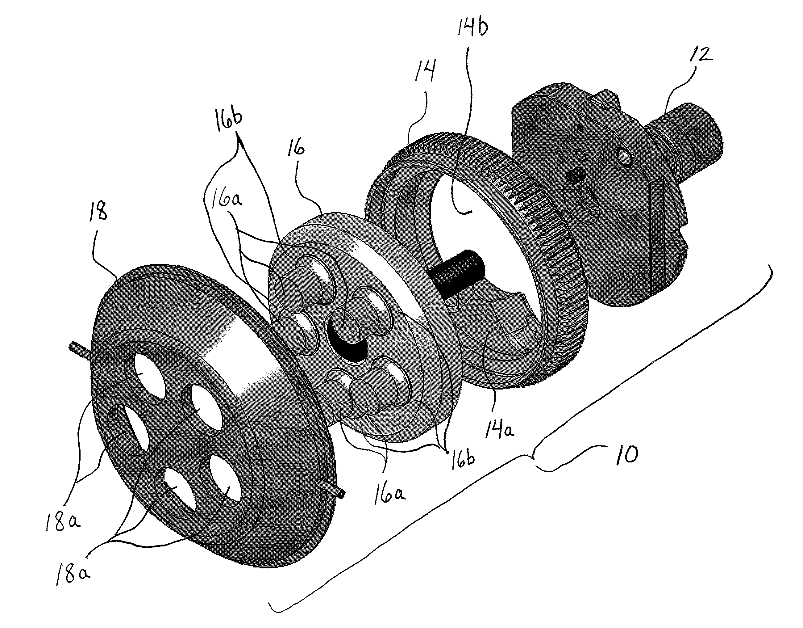
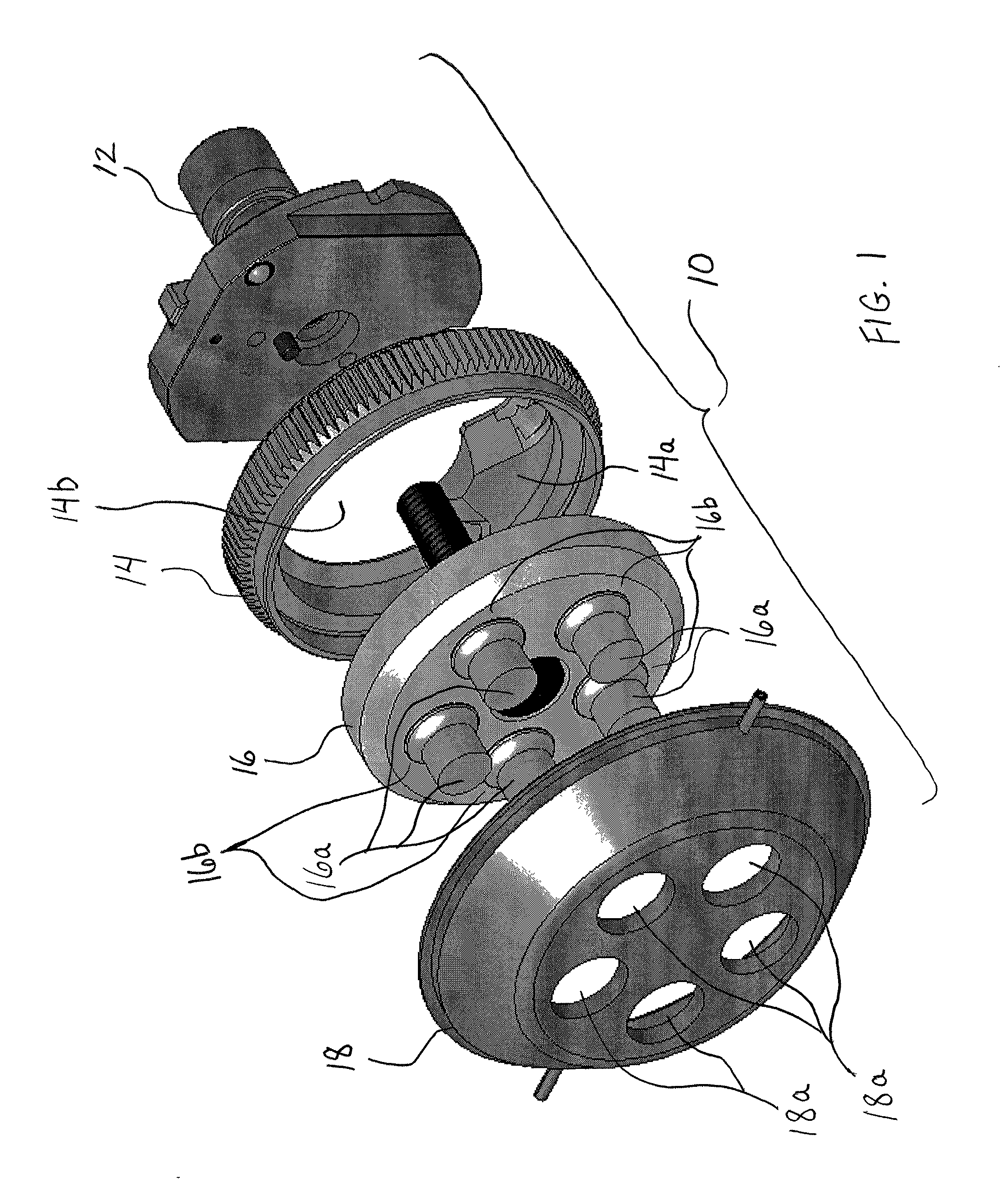
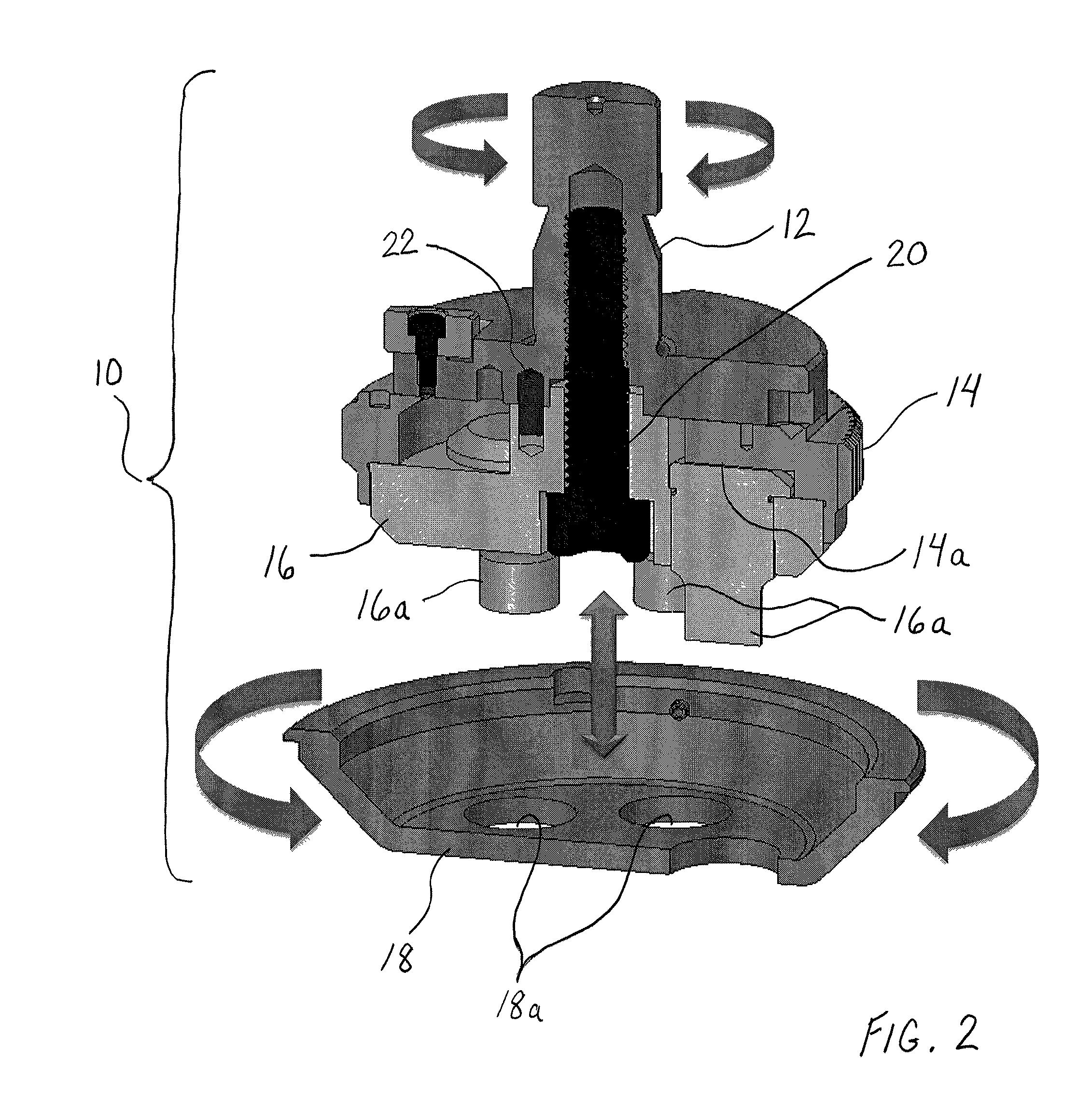
[0022]The following detailed description should be read with reference to the drawings, in which like elements in different drawings are numbered identically. The drawings depict selected embodiments (unless otherwise described), and thus are not intended to limit the scope of the invention. It will be understood that embodiments shown in the drawings and described below are merely for illustrative purposes, and are not intended to limit the scope of the invention as defined in the claims.

[0023]As described above, adaptors have been designed for multi-tools to facilitate their interfacing (i.e., functioning) with particular designs of punch presses. As further described, the typical reason why the multi-tools would not normally function with the particular press designs is because the presses and multi-tools originate from different manufacturers. In order to appreciate the general design and functioning of known adaptors, elements of a multi-tool are initially described below. Howe...


PUM

PropertyMeasurementUnit
Angleaaaaaaaaaa
Forceaaaaaaaaaa
Pressureaaaaaaaaaa

Abstract

A multi-tool adaptor which enhances overall performance of the multi-tools on which the adaptor is intended and the punch presses with which the multi-tools are desired to interface. The intermediary components relating to the functioning of the multi-tool involve one area of consideration regarding the adaptor design. Another area of consideration for the adaptor design involves the manner by which the stripper plate is operably coupled to the punch holder.

Description

FIELD OF INVENTION[0001]The present invention relates generally to tooling used with fabrication equipment or machines. More particularly, this invention relates to multi-tools and an adaptor configured therefor so the multi-tools are made compatible with one or more designs of fabrication equipment or machines.BACKGROUND[0002]Sheet metal and other workpieces can be formed into a wide range of useful products. Fabrication equipment or machines are often used for such processes. For example, in the case of punch presses, the press is typically configured to hold a plurality of tools for forming a variety of shapes and sizes of indentations and / or holes in the sheet metal and workpieces. Tools of this sort commonly include at least one punch assembly and corresponding die.[0003]A conventional punch assembly typically includes a punch guide, a punch holder, and a punch. When the punch assembly is mounted in a punch press, and located in a working position of the press, i.e., beneath a ...

Claims


Application Information

Patent Timeline
IPC IPC(8): B23Q3/18
CPCB23Q3/18B21D28/12B21D28/36B21D45/006Y10T483/10Y10T483/15
Inventor ROSE, CHRISTOPHER J.O'BRIEN-JONES, DAMIAN
Owner WILSON TOOL INT
Why Eureka
Try Eureka