
Medical treatment tool

a technology of treatment tool and retraction rod, which is applied in the field of medical treatment tool, can solve the problems of inability to reproduce the angle of mounting the converter on the retractor main body, difficulty in accessing diseased areas, and change in the positional relationship between the organ and the port, and achieve the effect of stably performing the treatment operation

Active Publication Date: 2015-08-27
SUMITOMO BAKELITE CO LTD
View PDF4 Cites 3 Cited by
  • Summary
  • Abstract
  • Description
  • Claims
  • Application Information

AI Technical Summary

Benefits of technology

The present invention provides a medical treatment tool that allows for stable and repeated access to organs through multiple ports. The tool prevents fluctuations in the position between the retractor and the ports, and changes in the arrangement positions of the ports can be easily achieved by adjusting the installation angle of the converter. This allows for precise placement of the ports in relation to the retractor, regardless of which organ they are being accessed during treatment. The invention also allows for various accesses to different organs, making it easy to perform complex procedures while maintaining stability.

Problems solved by technology

Therefore, it is difficult to access diseased areas depending on the position of the diseased areas which are, for example, positioned on an extension line of two ports.
In addition, the instrument of Patent Document 2 is configured such that the converter is installed on the retractor main body at the arbitrary angle, and therefore, there is no reproducibility at the angle of mounting the converter on the retractor main body.
For this reason, there is a problem in that the positional relationships between organs and ports change each time when taking out an excised tissue by removing the converter from the retractor main body many times.

Method used


Image

  • Medical treatment tool
  • Medical treatment tool
  • Medical treatment tool

Examples


Embodiment Construction

[0031]Hereinafter, embodiments of the present invention will be described based on the drawings. In all of the drawings, the same components are given the same reference numerals and the description will not be repeated.

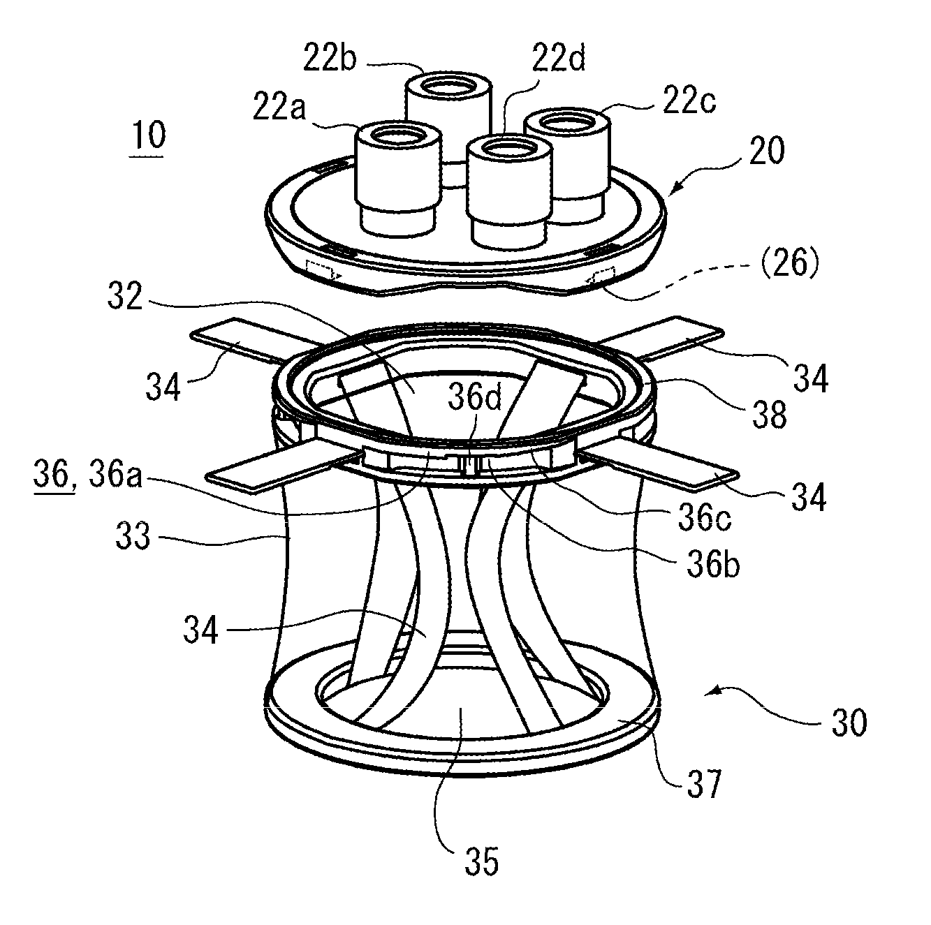
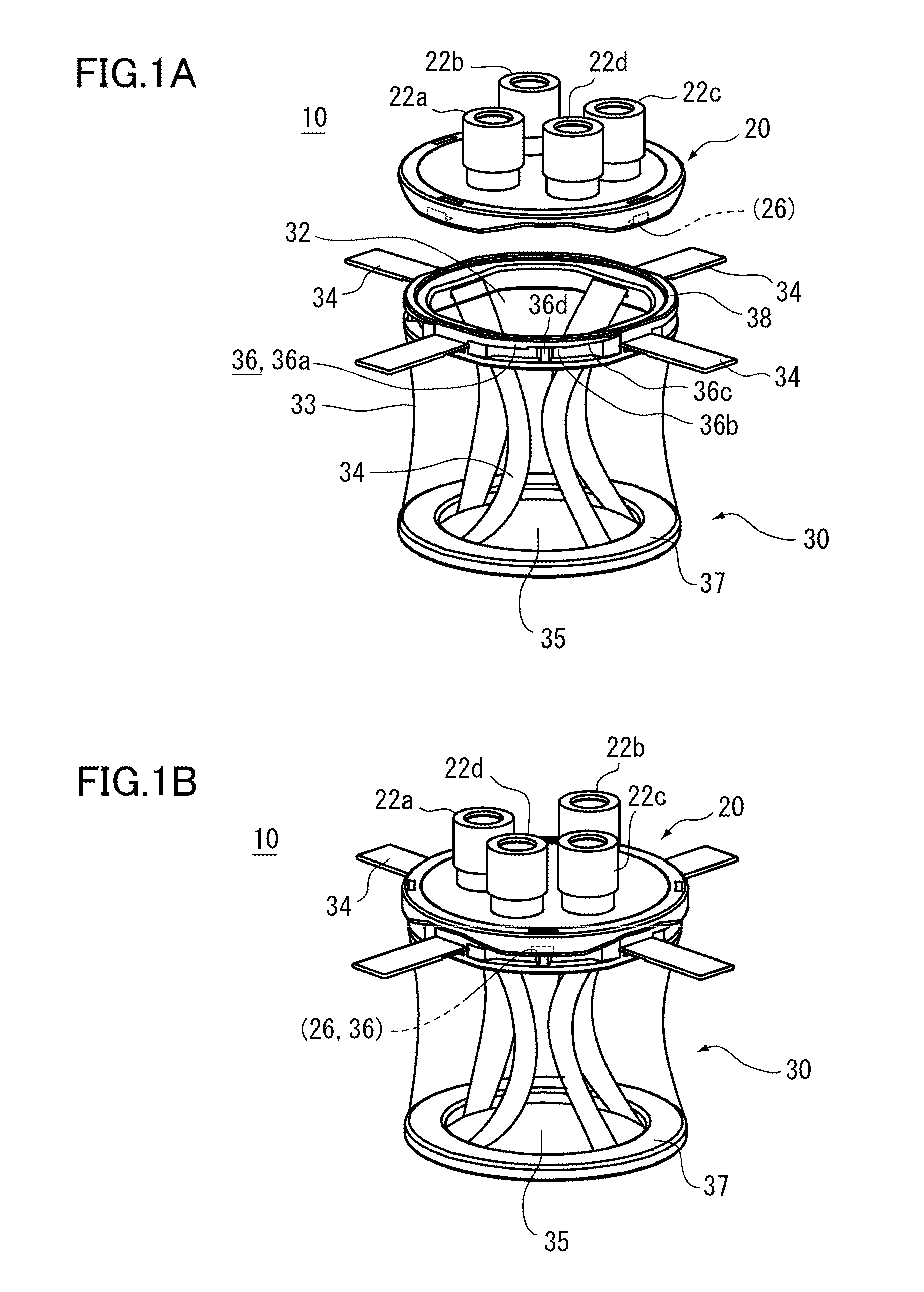
[0032]FIGS. 1A and 1B are perspective views showing an example of a medical treatment tool 10 according to the embodiment of the present invention. More specifically, FIG. 1A shows a state where a converter 20 is separated from a retractor main body 30 and FIG. 1B shows a state where the converter 20 is installed on the retractor main body 30.

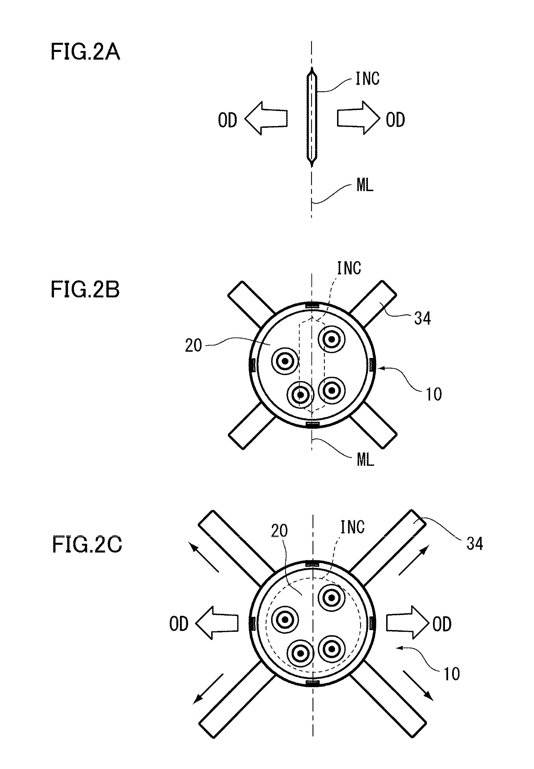
[0033]FIGS. 2A to 2C are plan views showing a state where the medical treatment tool 10 of the present embodiment is placed in an incision INC. FIG. 2A is a plan view of the incision INC which is formed to pass through an umbilicus BT (which is not shown in FIG. 2A; refer to FIG. 5) along a median line ML of a patient. An opening direction OD in which the diameter of the incision INC is expanded using the medical treatment tool ...


PUM


Abstract

A medical treatment tool (10) includes a retractor main body (30) and a converter (20). The retractor main body (30) forms a cylindrical shape and is placed in an incision. The converter (20) is detachably installed on an opening end (32) of the retractor main body (30) and closes the opening end (32). Ports (22a) to (22d) through which treatment tools are respectively inserted into the retractor main body (30) are provided in a plurality of sites of the converter (20). The converter (20) can be installed on the opening end (32) at an installation angle which is selected from a plurality of angles. The positional relationships of the ports (22a) to (22d) with respect to the retractor main body (30) when the converter (20) is installed on the opening end (32) at the respective installation angles become different from each other.

Description

TECHNICAL FIELD[0001]The present invention relates to a medical treatment tool which is placed in an incision when used.BACKGROUND ART[0002]In laparoscopic surgery, a single hole-type surgery through which the surgery is performed by inserting a plurality of treatment tools such as forceps or optical devices through an incision has been performed. The surgery method has a great cosmetic advantage since only an incision remains on the body surface of a patient. Generally, the incision is formed in the umbilicus in order to prevent the incision from being conspicuous after the surgery.[0003]In recent years, exclusive instruments for inserting a plurality of treatment tools in an incision has been developed (refer to Patent Documents 1 and 2). These instruments include a cylindrical retractor main body that holds the incision in an opened state and a lid-like converter having a plurality of small holes (ports) through which the treatment tools are respectively inserted.[0004]Meanwhile,...

Claims


Application Information

Patent Timeline
Patent Type & Authority Applications(United States)
IPC IPC(8): A61B17/02A61B17/34
CPCA61B17/0218A61B17/0293A61B17/3423A61B2017/347A61B2017/3449A61B2017/0225A61B17/3498A61B2017/3466A61B2090/0811
Inventor KANEHIRA, EIJIYAMABE, ETSUROSUZUKI, MINORU
Owner SUMITOMO BAKELITE CO LTD
Learn More