
Low cross-talk differential microstrip lines for high-frequency signal transmission

a high-frequency signal and differential microstrip technology, applied in the field of transmission lines, can solve the problems of inability to use a periodical structure as a main signal transmission body, inconceivable use of this kind of circuit, and inapplicability, so as to increase the self-inductance of the circuit, reduce the cross-talk, and increase the current density

Active Publication Date: 2015-08-20
WU CHIA HO
View PDF4 Cites 0 Cited by
  • Summary
  • Abstract
  • Description
  • Claims
  • Application Information

AI Technical Summary

Benefits of technology

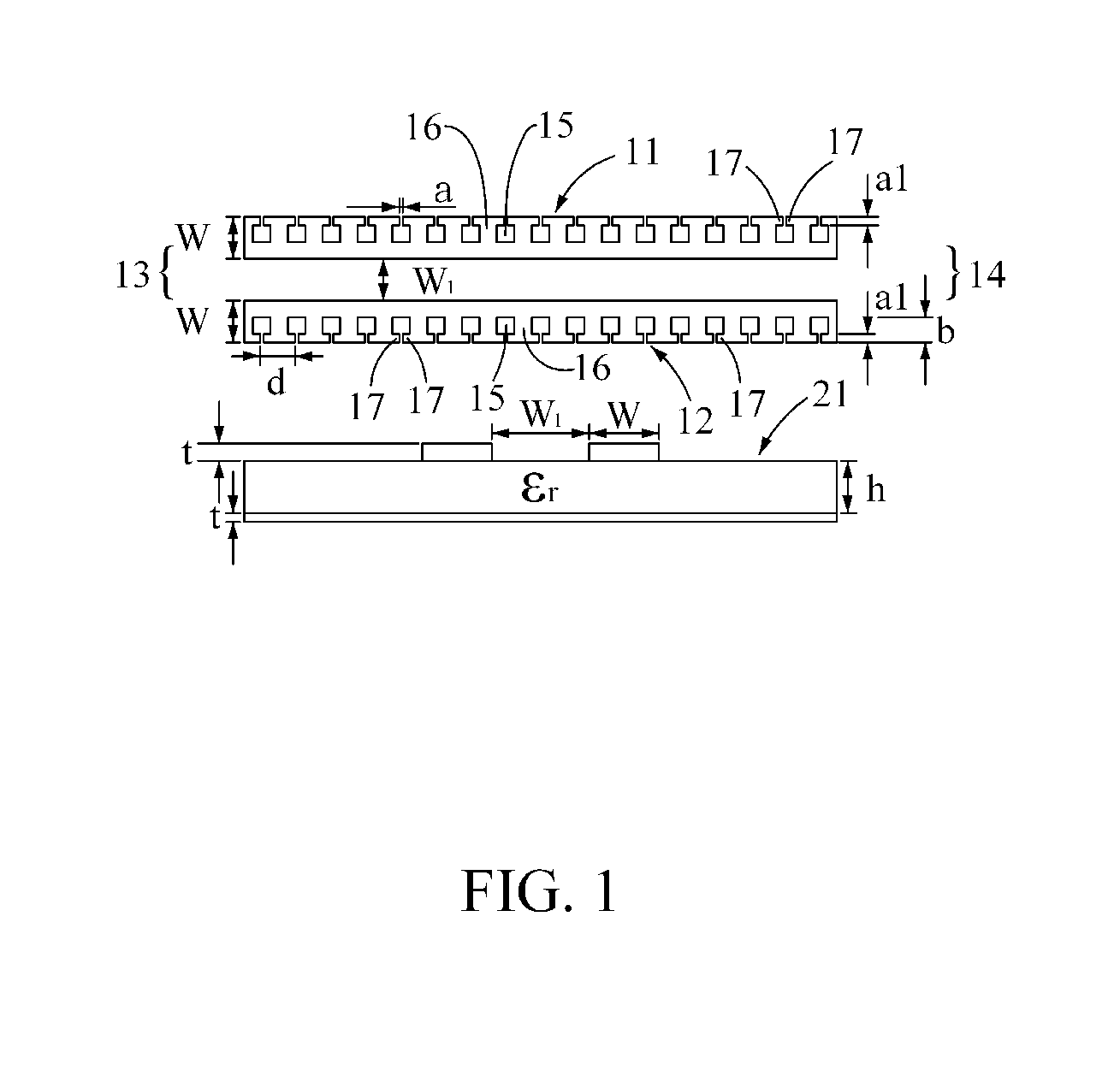
The present invention provides a pair of differential microstrip lines with low cross-talk for high-frequency signal transmission. This is achieved by etching periodical subwavelength corrugations along the edges of the microstrip lines and introducing the current at the edges into the slots to form an approximately closed loop. This subwavelength structure is favorable to increase the self-inductance of the circuit and confine the magnetic field around the lines, which could greatly reduce thecross-talk due to the mutual inductance between the adjacent circuits. The low cross-talk differential microstrip lines have the advantages of effective solution of cross-talk and mode conversion effect to improve signal transmission quality and reduce the size of the circuit board.

Problems solved by technology

A periodical structure in the conventional microstrip circuits is usually for band stop filters; however, it is not so practical because of its long length.
As the purposes of the periodical structures in the conventional microstrip circuits are deeply rooted in those skilled in the art, it is impossible for them to use a periodical structure as a main signal transmission body.
Additionally, the circuit design softwares used by them usually do not support this kinds of circuits; therefore, it is inconceivable for them to use this kinds of circuits as a signal line.
First one is to bend the differential pair and the single-ended line many turns to reduce cross-talk; however, it may generate the common mode signal in the differential pair, which is unfavorable to the operation of the whole circuit.
The other one is to install additional guard trace grounded lines between adjacent loops; however, it could result in two obvious shortcomings First, the areas of the loops cannot be effectively deceased.
Second, the guard trace grounded lines can block out the electrical field between the two loops, but cannot effectively suppress the mutual inductance between lines.
So as to reduce the circuit area of the differential pair, the distances between the differential pair and other transmission lines need to be further decreased, which will bring about serious cross-talk and mode conversion effect between the differential signal and common mode signal.

Method used


Image

  • Low cross-talk differential microstrip lines for high-frequency signal transmission
  • Low cross-talk differential microstrip lines for high-frequency signal transmission
  • Low cross-talk differential microstrip lines for high-frequency signal transmission

Examples


first embodiment

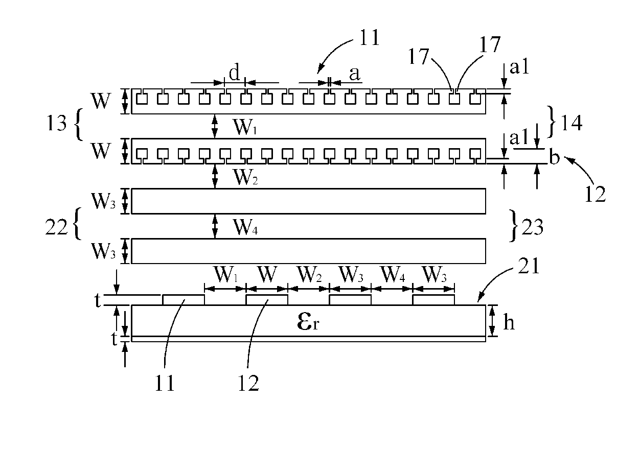
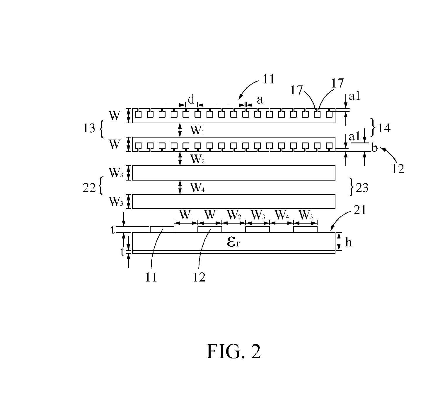
[0047]the present invention is, as shown in FIG. 1, a differential pair of microstrip lines with the opening-type periodical subwavelength configuration, wherein the differential pair is composed of two microstrip lines, the first microstrip line 11 and the second microstrip line 12, with periodical subwavelength configurations. The signals are inputted into the first terminal 13 and outputted from the second terminal 14. The signal transmitted via the first microstrip line 11 has a 180° phase difference from the signal transmitted via the second microstrip line 12 (i.e.: the signal transmitted via the first microstrip line 11 is the complementary signal of that transmitted via the second microstrip line 12.). The configuration of the slots comprises a plurality of rectangular convex bodies 16 continuously and periodically combined with a plurality of rectangular concave bodies 15. Two adjacent rectangular convex bodies 16 are divided by one rectangular concave body 15, and each of ...

second embodiment

[0053]the present invention is, as shown in FIG. 5, a differential pair with the hairpin-type periodical subwavelength configuration. The differential pair is composed of two microstrip lines, the first microstrip line 11 and the second microstrip line 12, with periodical subwavelength configurations. The signals are inputted into the first terminal 13 and outputted from the second terminal 14. The signal transmitted via the first microstrip line 11 has a 180° phase difference from the signal transmitted via the second microstrip line 12 (i.e.: the signal transmitted via the first microstrip line 11 is the complementary signal of that transmitted via the second microstrip line 12.). The configuration of the slots comprises a plurality of Z-shaped convex bodies 20 arranged continuously and periodically, and each of the Z-shaped convex bodies 20 comprises two extended portions 17, 18, wherein the first extended portion 17 parallel extends from the opening of one slot to the center of ...

third embodiment

[0060]the present invention is, as shown in FIG. 10, a differential pair with the slot-type periodical subwavelength configuration. The differential pair is composed of two microstrip lines, the first microstrip line 11 and the second microstrip line 12, with the slot-type periodical subwavelength configuration. The signals are inputted into the first terminal 13 and outputted from the second terminal 14. The signal transmitted via the first microstrip line 11 has a 180° phase difference from the signal transmitted via the second microstrip line 12 (i.e.: the signal transmitted via the first microstrip line 11 is the complementary signal of that transmitted via the second microstrip line 12.). The configuration of the slots comprises a plurality of rectangular convex bodies 16 continuously and periodically combined with a plurality of rectangular concave bodies 15, and the two adjacent rectangular convex bodies 16 are divided by one rectangular concave body 15, and the interval of t...


PUM


Abstract

The present invention discloses a pair of differential microstrip lines with low cross-talk for high-frequency signal transmission. The pair of microstrip lines comprises two microstrip lines. The first microstrip line is used to transmit the first transmission signal. The second microstrip line is parallel to the first microstrip line and used to transmit the second transmission signal. The first transmission signal is the complementary signal of the second transmission signal and has a 180° phase difference from the second transmission signal. Particularly, there are a plurality of slots periodically arranged on the outer sides of the first and the second microstrip lines to form a subwavelength configuration. The subwavelength configuration is to make the periodical arrangement length of these slots shorter than the wavelengths of the first and the second transmission signals. These slots can provide subwavelength confinement for enhancing electromagnetic wave.

Description

CROSS-REFERENCE TO RELATED APPLICATION[0001]This application claims the benefit of Taiwan Patent Application No. 103104920, filed on Feb. 14, 2014, in the Taiwan Intellectual Property Office, the disclosure of which is incorporated herein in its entirety by reference.BACKGROUND OF THE INVENTION[0002]1. Field of the Invention[0003]The present invention generally relates to a transmission line, in particular to low cross-talk differential microstrip lines for high-frequency signal transmission.[0004]2. Description of the Related Art[0005]In recently years, since signal transmission rate becomes higher, and the size of electronic products becomes smaller, electronic circuits tend to be designed to be more intensive. Due to the high integrity, the cross-talk between electronic circuits becomes more serious than before. When signals are transmitted via transmission lines, the adjacent transmission lines will be interfered by each other due to the electromagnetic wave coupling phenomenon;...

Claims


Application Information

Patent Timeline
Patent Type & Authority Applications(United States)
IPC IPC(8): H01P3/08
CPCH01P3/081H01P3/026H05K1/0245
Inventor WU, CHIA-HO
Owner WU CHIA HO
Learn More