Electronic device with a fold mode and an unfold mode

Active Publication Date: 2015-08-20
WISTRON CORP
View PDF8 Cites 6 Cited by
  • Summary
  • Abstract
  • Description
  • Claims
  • Application Information

AI Technical Summary

Benefits of technology

The present invention is an electronic device that provides support for a flexible display panel and allows it to show a flat surface when unfolded. The device uses rotary axles to switch between a folded mode and an unfolded mode for the display module, and between a storage mode and an operation mode for the input module. The input module and display module can be stacked up to minimize the device's configuration. The invention has the advantage of providing preferred level support and convenient storage function, and allows for easy switching between display and input modes based on user demand.

Problems solved by technology

However, the conventional flex mechanism cannot provide effective support to the flexible displaying panel when the electronic reading device is unfolded, and the flexible displaying panel is damaged easily by unexpected pressure.
Thus, design of a flex mechanism with a fold mode and an unfold mode and capable of applying preferred support to the flat flexible displaying panel and an electronic device with the foresaid flex mechanism is an important issue of machinery design industry.

Method used


Image

  • Electronic device with a fold mode and an unfold mode
  • Electronic device with a fold mode and an unfold mode
  • Electronic device with a fold mode and an unfold mode

Examples


first embodiment

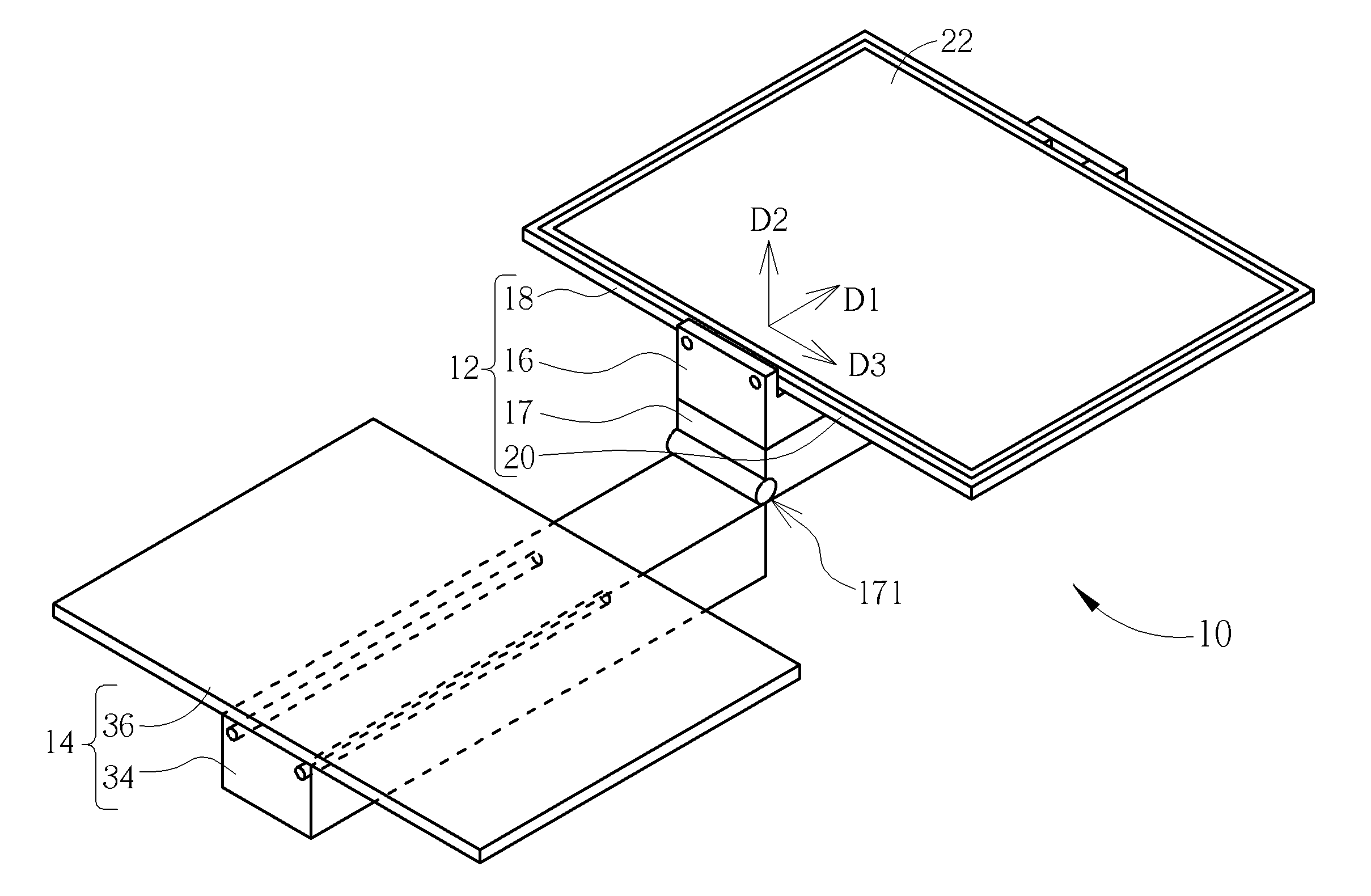
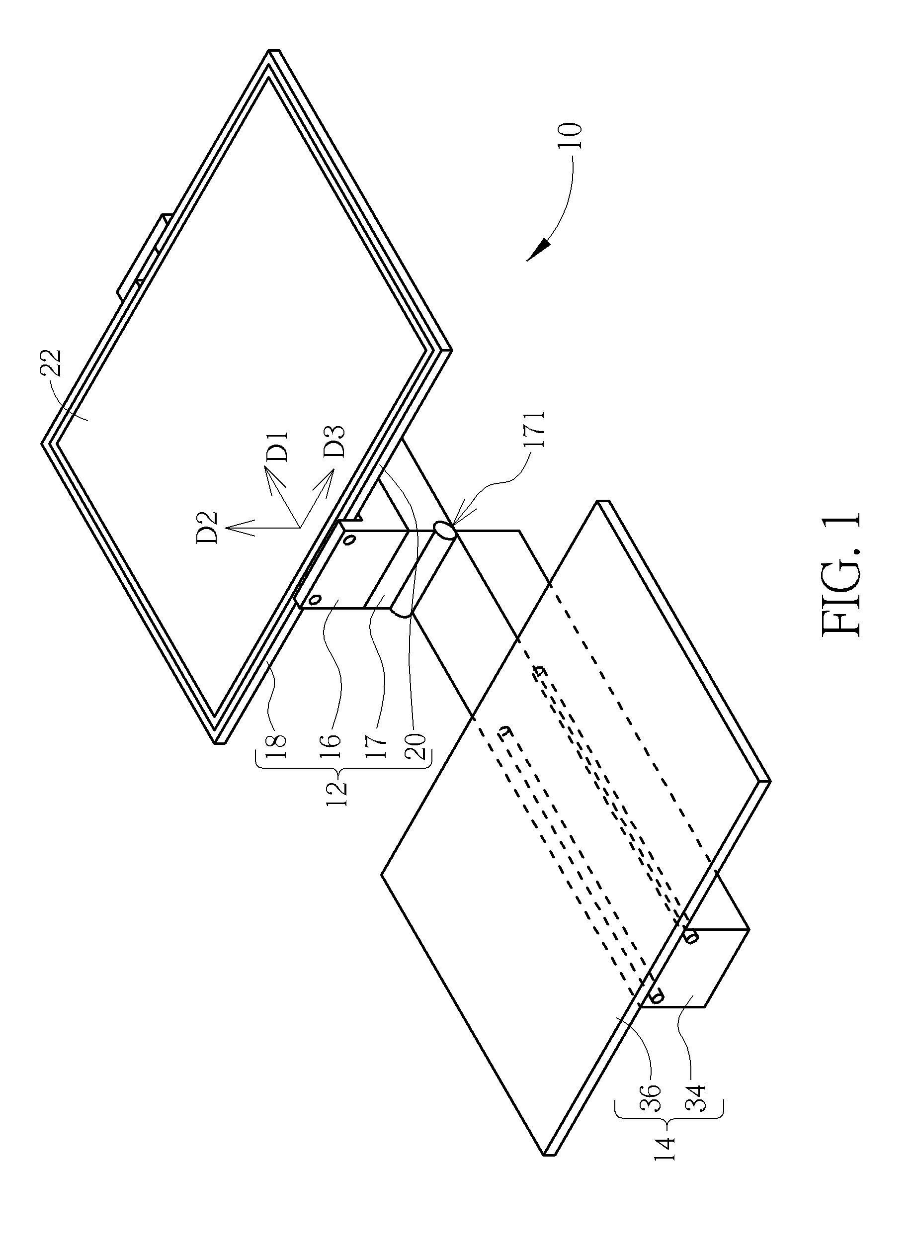
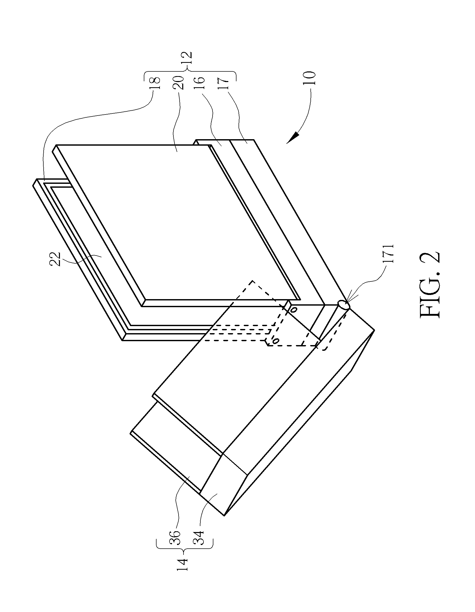
[0040]Please refer to FIG. 1 and FIG. 2. FIG. 1 and FIG. 2 respectively are diagrams of an electronic device 10 in different modes according to the present invention. The electronic device 10 includes a display module 12 and an input module 14. The input module 14 can rotate relative to the display module 12 to vary external form of the electronic device 10, which can be switched between a fold mode and an unfold mode. The display module 12 includes a base 16, a bridging component 17, a first connecting component 18 and a second connecting component 20. The base 16 is movably disposed on the bridging component 17. The first connecting component 18 and the second connecting component 20 respectively pivot to opposite sides of the base 16, which means the second connecting component 20 is rotatably connected to the first connecting component 16 via the base 16. The display module 12 further includes a flexible displaying panel 22. Opposite sides of the flexible displaying panel 22 are...

second embodiment

[0049]Please refer to FIG. 11. FIG. 11 is a diagram of the electronic device 10 in another mode according to the present invention. The input unit 36 not only can upwardly rotate relative to the body 34 (such as the position shown in FIG. 8), but also can downwardly rotate relative to the body 34 so as to perform the input module 14 as an inverted U-shaped form (which has a downward opening). Assembly application of the body 34 and the input unit 36 is not limited to the above-mentioned embodiment, and depends on actual demand.

[0050]Please refer to FIG. 12. FIG. 12 is a partial structural diagram of the electronic device 10 according to the second embodiment of the present invention. The bridging component 17′ further includes a guiding slot structure 38, and the rotary mechanism 26 is disposed on an end of the guiding slot structure 38. The guiding component 24 is slidably disposed inside the guiding slot structure 38. The base 16 can move and rotate relative to the bridging compon...


PUM


Abstract

An electronic device with a fold mode and an unfold mode includes a display module and an input module. The display module includes a first connecting component, a second connecting component and a flexible displaying panel. The second connecting component rotates relative to the first connecting component via a first direction to form as the fold mode or the unfold mode. The flexible displaying panel is disposed on the first connecting component and the second connecting component. The flexible displaying panel is bent to be U-shaped when the display module is formed as the fold mode. The flexible displaying panel is flat when the display module is formed as the unfold mode, and a planar normal vector points toward a second direction. The input module is rotatably connected to the display module via a third direction.

Description

BACKGROUND OF THE INVENTION[0001]1. Field of the Invention[0002]The present invention relates to an electronic device having a flexible displaying panel, and more particularly, to an electronic device having the flexible displaying panel and capable of being arbitrarily in a folded mode and to an unfolded mode.[0003]2. Description of the Prior Art[0004]Most of the available electronic reading devices utilize the conventional liquid crystal display to be the hard panel display. With advanced technology of the flexible displaying panel (such as the E-paper), the electronic reading device with the flexible displaying panel, which can be folded and unfolded, becomes trend of consumer's electronic product market. The conventional flexible panel utilizes a flex mechanism to reduce volume of the electronic reading device and overcome drawback of the flexible displaying panel unaligned with its supporter when the electronic reading device is unfolded. However, the conventional flex mechanis...

Claims


Application Information

Patent Timeline
IPC IPC(8): G06F1/16
CPCG06F1/1652G06F1/1656G06F1/1618G06F1/1681
Inventor HUANG, HAO-CHIENWANG, YI-KAICHEN, CHIA-HANLIN, CHUN-YUHSIEH, HSIN-YU
Owner WISTRON CORP
Why Eureka
Try Eureka