
System and method for testing of seal materials

a technology of sealing materials and testing methods, applied in the direction of machine parts testing, structural/machine measurement, instruments, etc., can solve the problems of leakage between the two mating flanges, the effect of the sealing member may diminish additionally, and the sealing force of the sealing member may also decreas

Inactive Publication Date: 2015-08-20
CATERPILLAR INC
View PDF3 Cites 11 Cited by
  • Summary
  • Abstract
  • Description
  • Claims
  • Application Information

AI Technical Summary

Benefits of technology

The patent describes a method for testing the performance of multiple sealing members. The method involves using a testing fixture made up of at least two blocks that are in contact with other fixtures. Each fixture has a groove where the sealing member is placed. The method involves controlling the temperature of the blocks to create different temperatures for the sealing members, and then passing fluid through the sealing members to monitor their performance. This method provides an effective way to test the performance of multiple sealing members simultaneously.

Problems solved by technology

Over a period of time, the effectiveness of the sealing member may diminish Additionally, a sealing force of the sealing member may also decrease, thereby leading to leakage between the two mating flanges in case of a surrounding fluid environment.
In addition, exposing the O-ring to an aging fluid, such as air, water, gasoline, brake fluid, or engine coolant may also affect the sealing force of the sealing member.
Accordingly, the testing procedures may provide erroneous evaluation of the sealing members.
However, the test procedure does not describe evaluating a performance of the sealing member in dynamic environmental conditions.

Method used


Image

  • System and method for testing of seal materials
  • System and method for testing of seal materials
  • System and method for testing of seal materials

Examples


Embodiment Construction

[0014]Reference will now be made in detail to specific aspects or features, examples of which are illustrated in the accompanying drawings. Wherever possible, corresponding or similar reference numbers will be used throughout the drawings to refer to the same or corresponding parts.

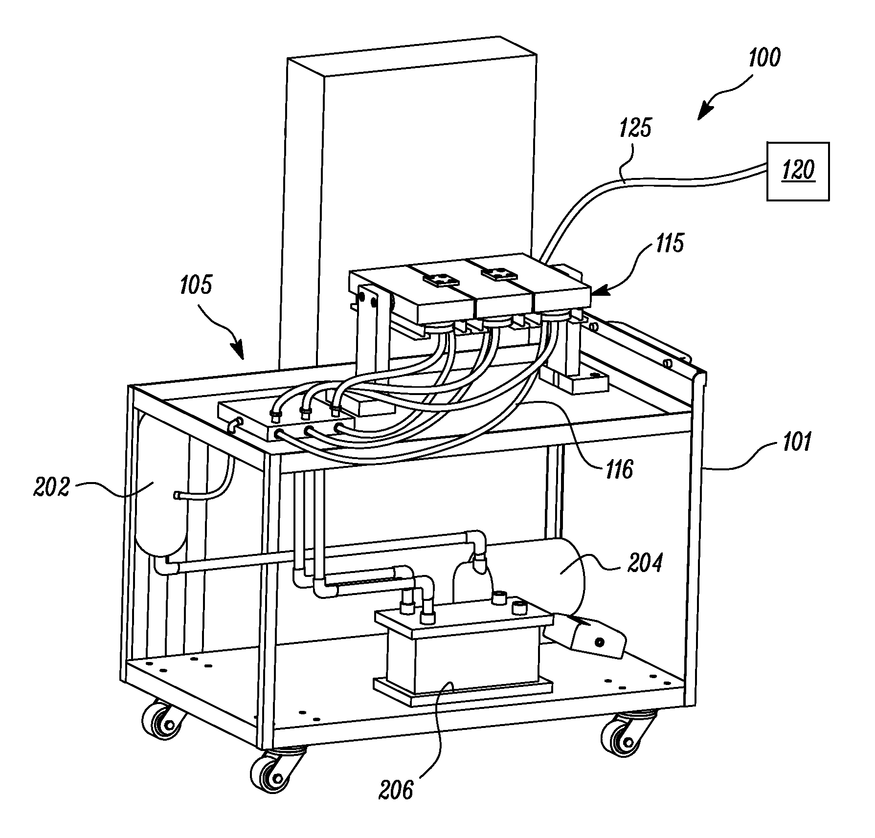
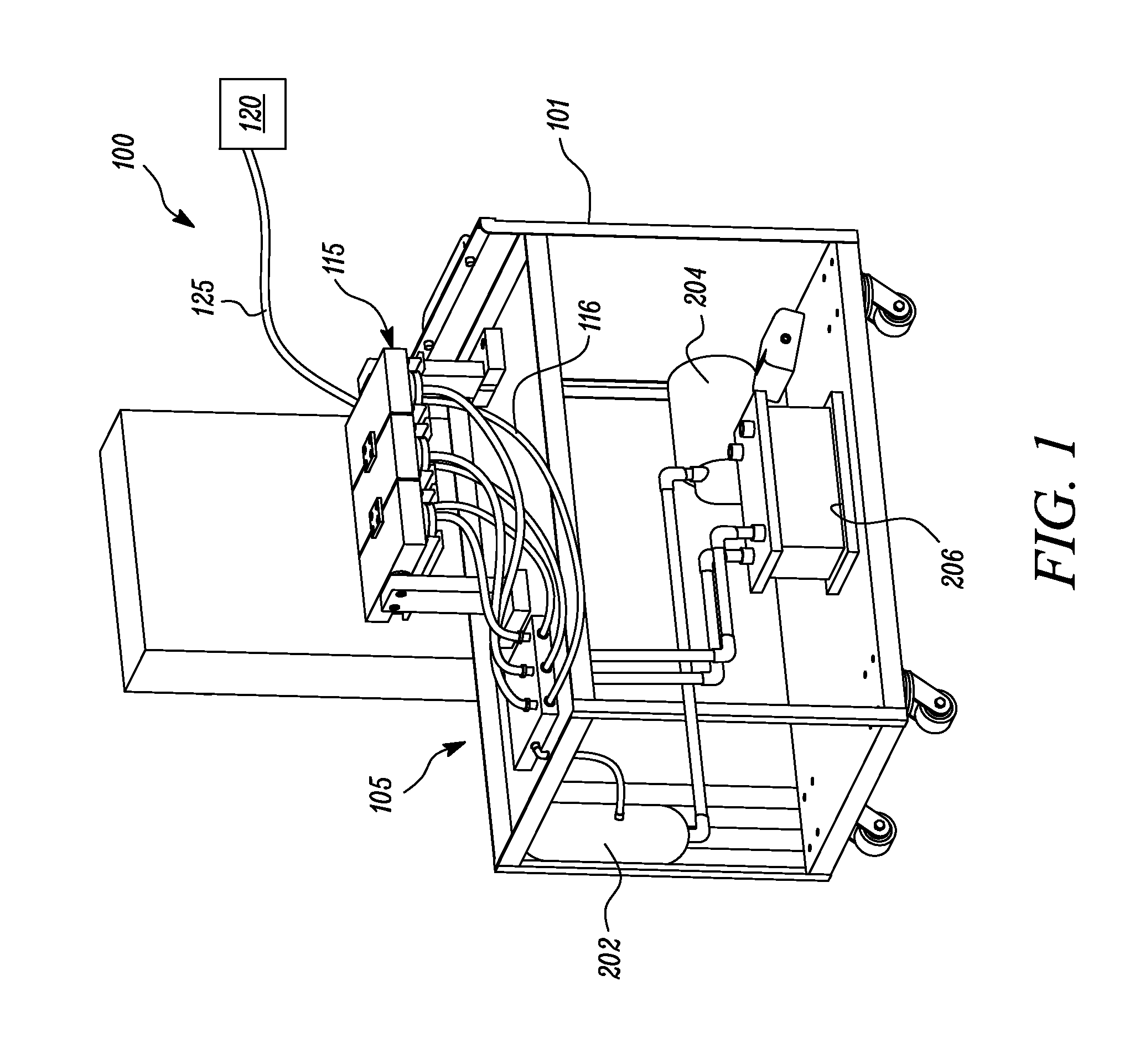
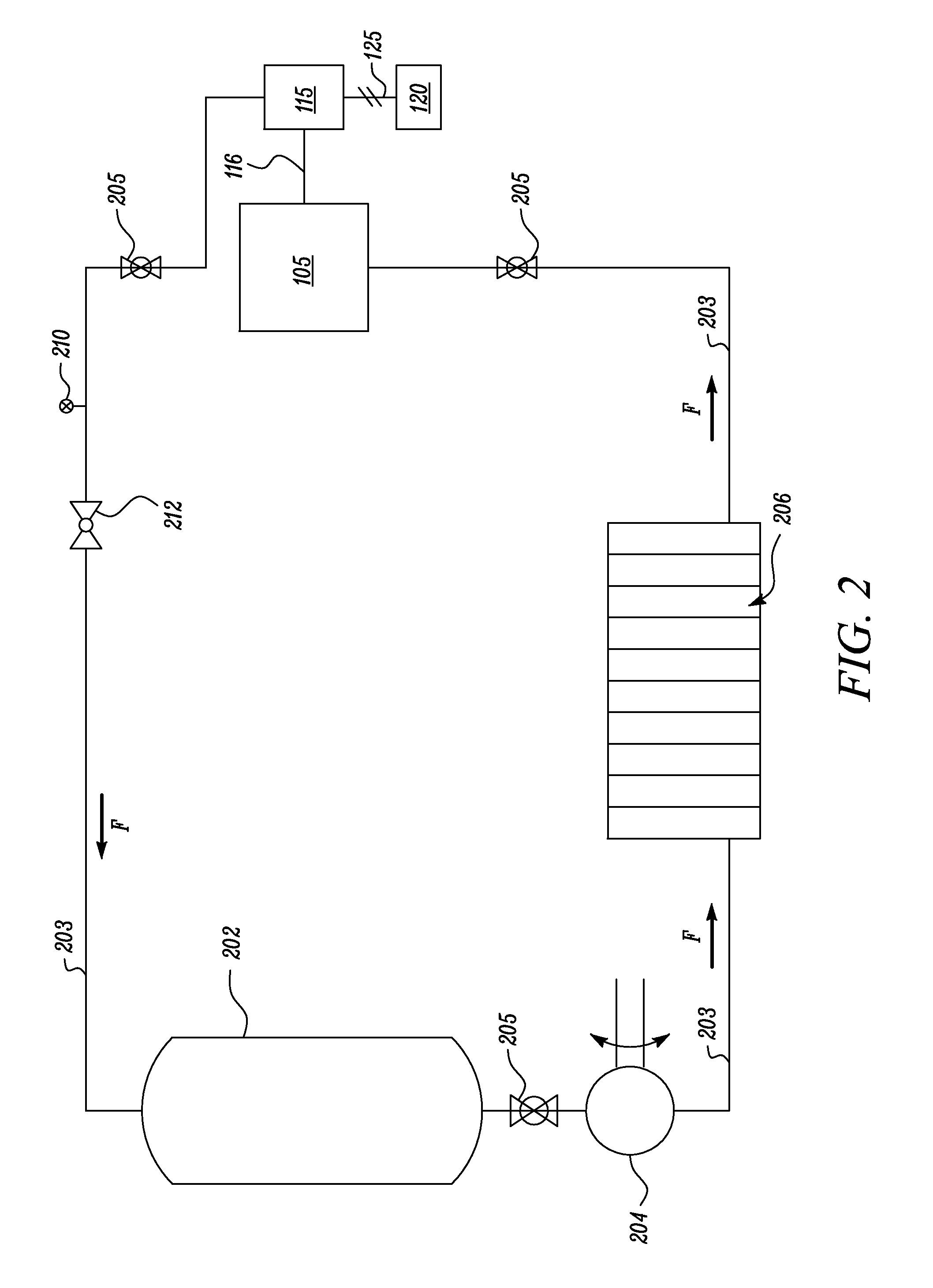
[0015]FIG. 1 illustrates an exemplary test apparatus 100, according to one embodiment of the present disclosure. The test apparatus 100 includes a test bench 101, a fluid manifold 105 placed on the test bench 101. FIG. 2 is an exemplary hydraulic circuit associated with the test apparatus 100. Referring to FIGS. 1 and 2, the fluid manifold 105 is configured to transfer a volume of an aging fluid, such as a coolant. Alternatively, the fluid may include a fuel, oil, an emulsion, and the like depending upon a test to be conducted by the test apparatus 100. The fluid manifold 105 is in communication with a testing fixture 115. In an embodiment, the fluid manifold 105 is coupled to the testing fixture 115 via ...


PUM


Abstract

A method for testing a performance of a plurality of sealing members includes providing a testing fixture including at least two blocks in a contacting relationship with a plurality of fixtures. Each of the plurality of fixtures defines a groove portion for receiving a sealing member. The method further includes connecting each of the plurality of fixtures with a fluid manifold. The method also includes controlling a temperature of each of the at least two blocks and the groove portion using a thermal device. Each of the at least two blocks and the groove portions are at temperatures different from each other. The method also includes passing a fluid through each of the plurality of fixtures so as to flow through a channel provided adjacent to and surrounding the groove portion. The method further includes monitoring a response of the sealing members to determine at least one performance parameter.

Description

TECHNICAL FIELD[0001]The present disclosure relates to a system and method for testing of seal materials, and more particularly to the testing of the seal materials in which fluid temperatures and seal temperatures can be varied.BACKGROUND[0002]Sealing members, such as, O-rings are commonly made of elastomeric materials. Elastomeric materials are generally conformable, free of porosity, and relatively resilient, thereby creating a relatively impermeable seal when positioned between two flat plates or flanges. Over a period of time, the effectiveness of the sealing member may diminish Additionally, a sealing force of the sealing member may also decrease, thereby leading to leakage between the two mating flanges in case of a surrounding fluid environment. A number of factors may affect a rate at which the sealing force of the sealing member reduces. For example, the type of elastomeric material of the sealing member, wear of the sealing member, environment of use of the sealing member...

Claims


Application Information

Patent Timeline
IPC IPC(8): G01M13/00G01M3/02
CPCG01M13/005G01M3/002
Inventor CLINE, JAY H.MOHAMMAD, KHALED M.ALAM, SARFRAZWOODS, ERIC LMONGER, JAMES F.D'SA, KEVIN
Owner CATERPILLAR INC
Learn More