
Oxygen transport membrane reactor based method and system for generating electric power

Active Publication Date: 2015-08-13
PRAXAIR TECH INC
View PDF7 Cites 27 Cited by
  • Summary
  • Abstract
  • Description
  • Claims
  • Application Information

AI Technical Summary

Benefits of technology

[0018]Yet still another characterization of the present invention is an oxygen transport membrane based power generation system comprising an oxygen transport membrane based power generation system comprising: (i) an oxygen transport membrane based reforming subsystem configured to produce a hydrogen-rich, high pressure synthesis gas stream from a hydrocarbon containing feed stream and steam; and (ii) an integrated gas turbine and steam turbine power cycle subsystem comprising a gas turbine fueled by the hydrogen-rich, high pressure synthesis gas produced in the oxygen transport membrane based reforming subsystem to generate steam, electric power, and a carbon dioxide containing effluent by combusting the hydrogen-rich, high pressure synthesis gas stream.
[0019]The present invention in one or more aspects can also be characterized as an oxygen transport membrane based co-product system comprising: (i) a coal gasification subsystem configured to produce a coal-derived, high pressure synthesis gas stream from a source of coal, steam and oxygen produced from cryogenic distillation of air; (ii) an oxygen transport membrane based reforming subsystem configured to produce a hydrogen-rich, high pressure synthesis gas stream from a hydrocarbon containing feed stream and steam; (iii) an oxygen transport membrane based power cycle subsystem comprising an oxygen transport membrane based boiler reactor configured to produce steam, electric power, and a carbon dioxide containing effluent by combusting a first synthesis gas feed stream at a pressure at least twice, in another embodiment at least 2.5 times, and in still another embodiment at least three times that of ambient pressure in the oxygen transport membrane based boiler reactor; and (iv) a fuel product or liquid product synthesis subsystem configured to produce a fuel product or liquid product from a second synthesis gas feed stream. A portion of the coal-derived, high pressure synthesis gas stream or a portion of the hydrogen-rich high pressure synthesis gas stream or a combination of portions of both high pressure synthesis gas streams form the first synthesis gas feed stream. In addition, a portion of the coal-derived, high pressure synthesis gas stream or a portion of the hydrogen-rich, high pressure synthesis gas stream or a combination of both high pressure synthesis gas streams form the second synthesis gas feed stream. The oxygen transport membrane based boiler reactor is preferably configured to combust the first synthesis gas to form an effluent having a heating value less than 100 Btu/scf and containing less than about 10% hydrogen.
[0020]Alternatively, the present invention may be characterized as an oxygen transport membrane based hybrid system comprising: (i) a coal gasification subsystem configured to produce a coal-derived, high pressure synthesis gas stream from a source of coal, steam and oxygen produced from cryogenic distillation of air; (ii) an oxygen transport membrane based reforming subsystem configured to produce a hydrogen-rich, high pressure synthesis gas stream from a hydrocarbon containing feed stream and steam; and (iii) a fuel product or liquid product synthesis subsystem configured to produce a fuel product or liquid product from a second synthesis gas feed stream. A portion of the coal-derived, high pressure synthesis gas stream or a portion of the hydrogen-rich, high pressure synthesis gas stream or a combination of portions of both high pressure synthesis gas streams form the second synthesis gas feed stream. In some preferred embodiments, the oxygen transport membrane based reforming system is also configured to provide at least three times the oxygen atoms in the hydrogen-rich high pressure synthesis gas stream than the oxygen atoms provided to the coal-derived high pressure synthesis gas by the oxygen produced from cryogenic distillation of air.
[0021]The present invention may also be characterized as an oxygen transport membrane based power generation system comprising: (i) a coal gasification subsystem configured to pro

Problems solved by technology

These systems can also be large and capital intensive due to the very large volume of nitrogen and oxygen contained in the flue gas, and the relatively small concentration of CO2 in the stream (4 to 15% by volume).
One of the recognized problems associated with oxygen transport membranes is that when operating in severe environments that result when combusting fuel at high pressure such as that in oxygen transport membrane based boiler, the reliability of the oxygen transport membranes typically suffer, resulting in more membrane failures and associated system operating downtime and maintenance costs.
In addition, oxygen transport membranes that are designed to operate in higher pressure environments typically require very thick support layers thus significantly increasing the cost of the oxygen transport membranes and associated reactors.
Regulating or reducing the high pressure gasifier stream involves specialized equipment and adversely impacts the overall econom

Method used


Image

  • Oxygen transport membrane reactor based method and system for generating electric power
  • Oxygen transport membrane reactor based method and system for generating electric power
  • Oxygen transport membrane reactor based method and system for generating electric power

Examples


Example

Oxygen Transport Membrane Based Steam Bottoming Cycle

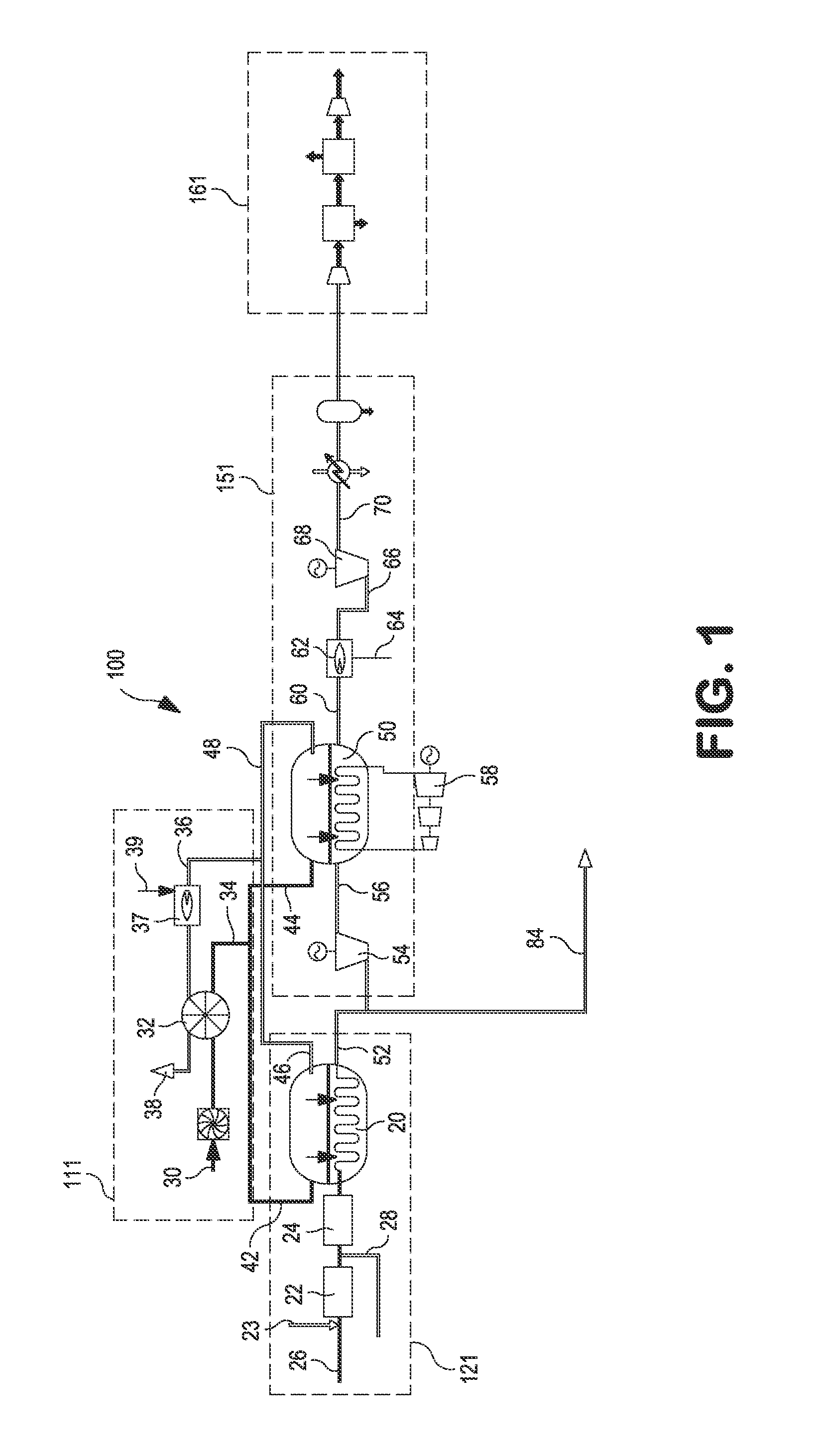
[0029]In a broad sense, FIG. 1 is a block diagram illustrating a carbon capture enabled oxygen transport membrane based steam bottoming cycle system 100 for producing electric power. The system 100 comprises an air supply and preheating subsystem 111; an oxygen transport membrane based synthesis gas subsystem 121; a power generation subsystem 151 comprising an oxygen transport membrane based boiler and a steam turbine; and a carbon dioxide purification unit or subsystem 161.

Air Preheat Subsystem

[0030]With reference to FIG. 1, the air supply and preheating subsystem 111 includes a source of feed air or other oxygen containing feed stream 30; a continuously rotating regenerative air preheater 32 configured to heat the source of feed air; and conduits for supplying the heated feed air stream 34 from the regenerative air preheater to the oxygen transport membrane based synthesis gas subsystem 121, and oxygen transport membrane based p...


PUM


Abstract

A carbon capture enabled system and method for generating electric power and/or fuel from methane containing sources using oxygen transport membranes by first converting the methane containing feed gas into a high pressure synthesis gas. Then, in one configuration the synthesis gas is combusted in oxy-combustion mode in oxygen transport membranes based boiler reactor operating at a pressure at least twice that of ambient pressure and the heat generated heats steam in thermally coupled steam generation tubes within the boiler reactor; the steam is expanded in steam turbine to generate power; and the carbon dioxide rich effluent leaving the boiler reactor is processed to isolate carbon. In another configuration the synthesis gas is further treated in a gas conditioning system configured for carbon capture in a pre-combustion mode using water gas shift reactors and acid gas removal units to produce hydrogen or hydrogen-rich fuel gas that fuels an integrated gas turbine and steam turbine system to generate power. The disclosed method and system can also be adapted to integrate with coal gasification systems to produce power from both coal and methane containing sources with greater than 90% carbon isolation.

Description

CROSS REFERENCE TO RELATED APPLICATIONS[0001]This application claims priority to and the benefit of U.S. provisional patent application Ser. Nos. 61 / 939,029 filed on Feb. 12, 2014 and 61 / 980,149 filed on Apr. 16, 2014, the disclosures of which are incorporated by reference herein.U.S. GOVERNMENT RIGHTS[0002]This invention was made with Government support under Cooperative Agreement No. DE-FC26-07NT43088, awarded by the United States Department of Energy. The Government has certain rights in this invention.FIELD OF THE INVENTION[0003]The present invention provides a method and system for producing a product or co-products from synthesis gas mixture, and more particularly for producing a fuel / liquid product and / or electric power from a synthesis gas mixture comprising a coal-derived synthesis gas and / or synthesis gas produced from an oxygen transport membrane based reforming reactor.BACKGROUND[0004]There is continuing interest in reducing the release of carbon dioxide to atmosphere fr...

Claims


Application Information

Patent Timeline
IPC IPC(8): F02C3/22H02K7/18C10J3/48F02C7/22B01D53/22C10J3/20F01D15/10F02C3/28
CPCF02C3/22F01D15/10H02K7/1823F02C3/28C10J2200/09B01D53/228C10J3/20C10J3/485F02W2746/00947F02C7/22C10J3/00C10J3/82F01K13/00F01K23/068C10J2300/165C01B3/382C01B3/48C01B13/0251C01B2203/0244C01B2203/0283C01B2203/0415C01B2203/06C01B2203/1241C01B2203/127C01B2203/84C01B2203/86Y02P20/129C10J2300/093C10J2300/0959C10J2300/0976C10J2300/1678Y02E20/16Y02E20/18Y02E20/32Y02E20/34Y02P30/00
Inventor KELLY, SEAN M.CHAKRAVARTI, SHRIKARLI, JUAN
Owner PRAXAIR TECH INC
Learn More