
Rotary shaving head having a locking retainer

a technology of locking retainer and shaving head, which is applied in the direction of metal working apparatus, etc., can solve the problems of limited space for applying visible markings onto the retainer, and the existing design of shaving head uses relatively complicated locking arrangement, so as to achieve the effect of individual disassembly and cleaning or maintenan

Inactive Publication Date: 2015-08-13
KONINKLJIJKE PHILIPS NV
View PDF7 Cites 9 Cited by
  • Summary
  • Abstract
  • Description
  • Claims
  • Application Information

AI Technical Summary

Benefits of technology

The present invention is related to a shaving head with a retainer that allows cut hairs and debris to pass through towards a collection chamber. The shaving head can be constructed in different forms, such as a spring-loaded cutter unit or a pivotable skin supporting rim. The retainer makes it easy to clean or maintain each cutter unit individually. The technical effects of the invention include improved shaving efficiency, flexibility with the shaver drive, and better follow-up of the skin during shaving.

Problems solved by technology

Existing designs of shaving head use relatively complicated locking arrangements to hold the components together.
Often, a user will not even realise that an additional disassembly step is possible or required and will attempt to clean the head in its assembled condition.
Nevertheless, the available space for application of visible markings onto a retainer is limited.

Method used


Image

  • Rotary shaving head having a locking retainer
  • Rotary shaving head having a locking retainer
  • Rotary shaving head having a locking retainer

Examples


Embodiment Construction

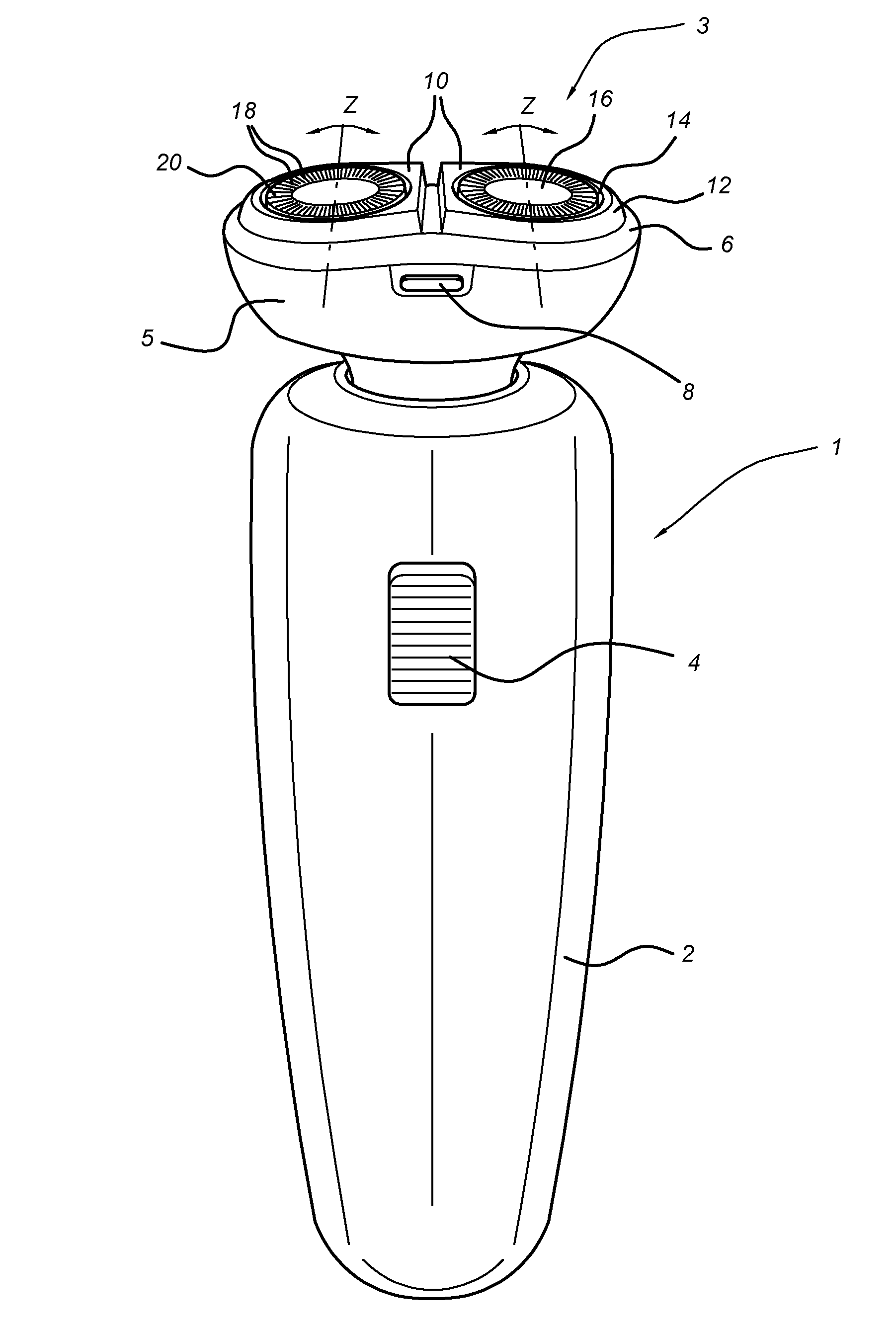
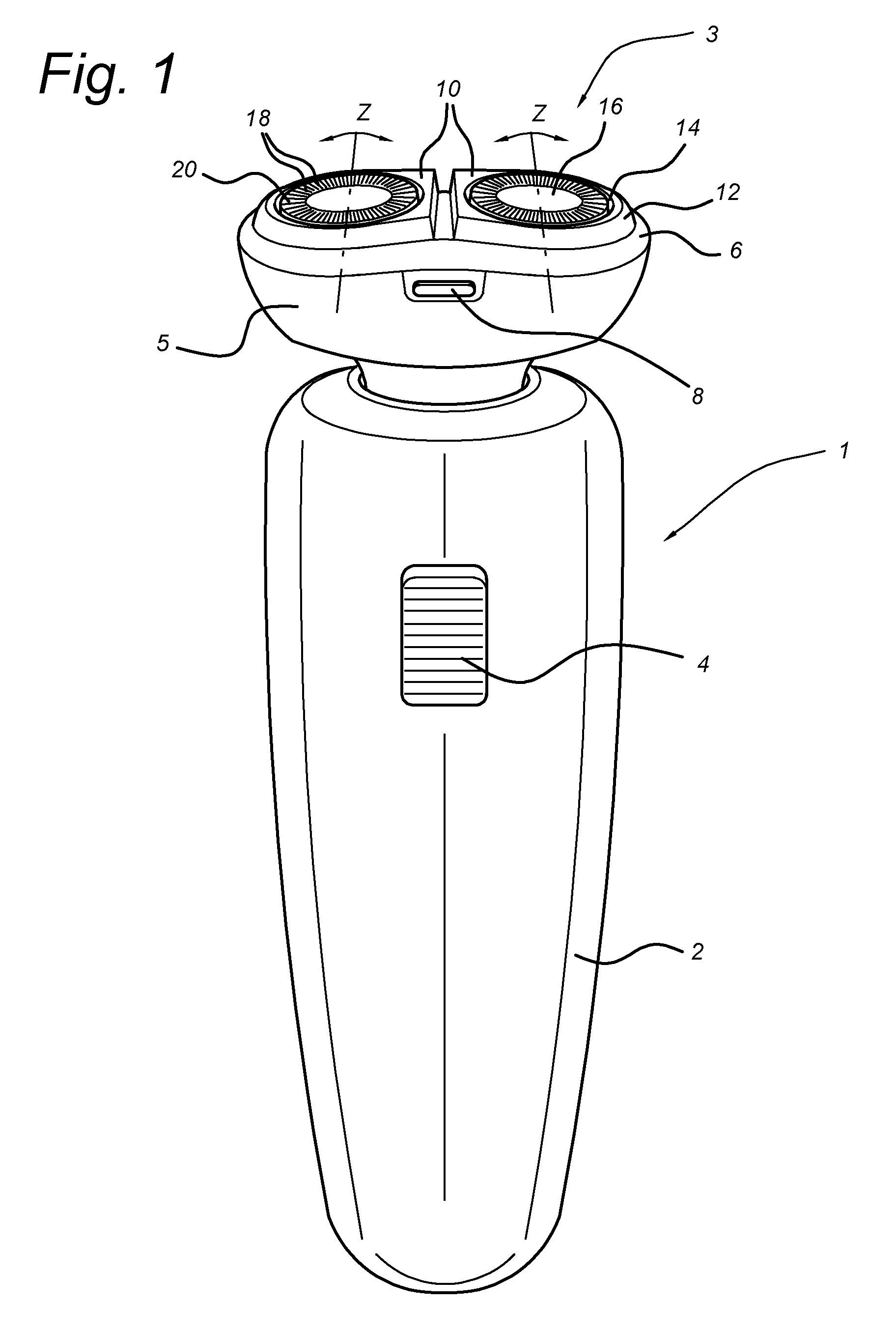
[0030]FIG. 1 shows a perspective view of a shaver 1 according to the invention.

[0031]The shaver 1 has a main body 2 and a head 3. In the body 2 are housed motor, transmission, power supply, control electronics and the like which are otherwise conventional and will not be described further. A switch 4 for activation of the shaver is provided on the front of the body 2. The head 3 comprises a first housing part 5 and a second housing part t 6 on which are mounted a pair of cutter units 10. Each cutter unit 10 comprises a support member 12 which has an opening 14 through which a cap 16 protrudes. The support members 12 are mounted to float with respect to the second housing part 6, whereby they pivot about a transverse axis Z. The cap 16 has slots 18 formed through its external surface 20 as is generally conventional. The second housing part 6 is connected to the first housing part 5 and can be released by a catch 8 which allows access to the rear side of the cutter units 10

[0032]FIG. ...


PUM


Abstract

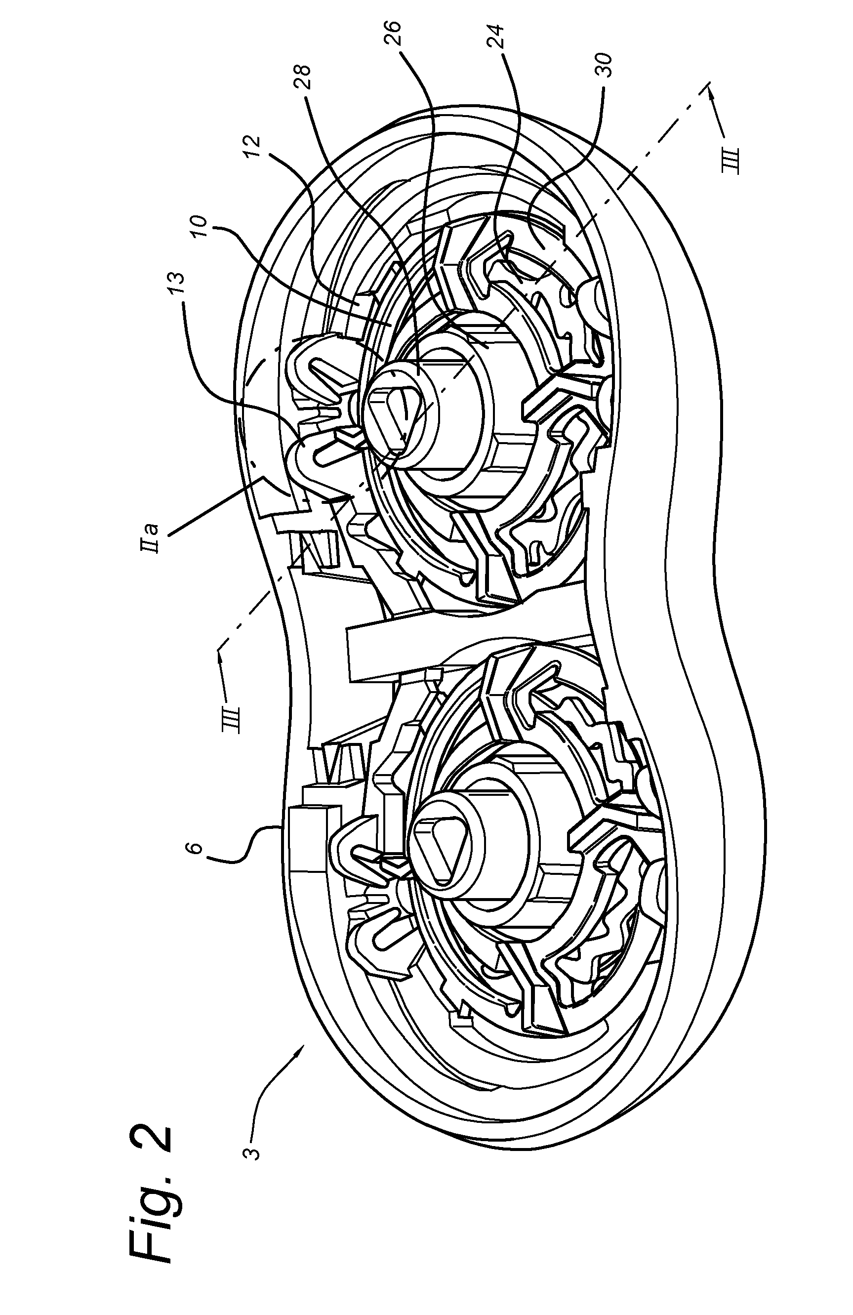
A rotary shaving head 3 has at least one cutter unit 10, each cutter unit comprising a cap 16 having an external surface 20 with hair-entry openings 18 for engaging the skin of a user; and a rotary cutter 24 having cutting elements 32 supported by a carrier 26, the rotary cutter being locatable within and rotatable with respect to the cap. The shaving head further comprises: a support member 12 for supporting the cutter unit; and a retainer 30, arranged to engage and lock with the support member by relative rotation therewith and retain the cap and the rotary cutter therebetween, wherein the retainer comprises an annular body 36, 38 defining a drive opening 42, the annular body being provided with one or more holes 40 allowing cut hairs to pass through. The holes are shaped as directional indicators indicating a direction of rotation of the retainer with respect to the support. As a result of the pro posed design, a user can identify the retainer as being a rotational component even though it is located within the support member. In an alternative embodiment, the retainer is provided with gripping formations which are formed as directional indicators.

Description

BACKGROUND OF THE INVENTION[0001]1. Field of the Invention[0002]The present invention relates to shaving devices of the rotary type and in particular to a rotary shaving head having at least one cutter unit and a retainer for locking the elements of the cutter unit together. The invention also relates to a shaver incorporating such a rotary shaving head.[0003]2. Description of the Related Art[0004]Electrical shavers are frequently used consumer items which generally comprise an assembly of moving and stationary elements that interact to cut the hairs at the surface of a user's skin. The shaving elements such as a cutter and cap or guard, have to be fixed to the body of the shaver. For greater comfort and convenience, the shaving elements may be resiliently mounted and are generally removable for cleaning and maintenance. In rotary shavers, the shaving elements usually comprise an outer cap and a rotating cutter located within the cap. The outer cap has apertures allowing hairs to pr...

Claims


Application Information

Patent Timeline
IPC IPC(8): B26B19/14
CPCB26B19/14B26B19/145
Inventor STEUR, JELTE
Owner KONINKLJIJKE PHILIPS NV
Learn More