
Component-mounting machine

Active Publication Date: 2015-08-06
FUJI MASCH MFG CO LTD
View PDF1 Cites 1 Cited by
  • Summary
  • Abstract
  • Description
  • Claims
  • Application Information

AI Technical Summary

Benefits of technology

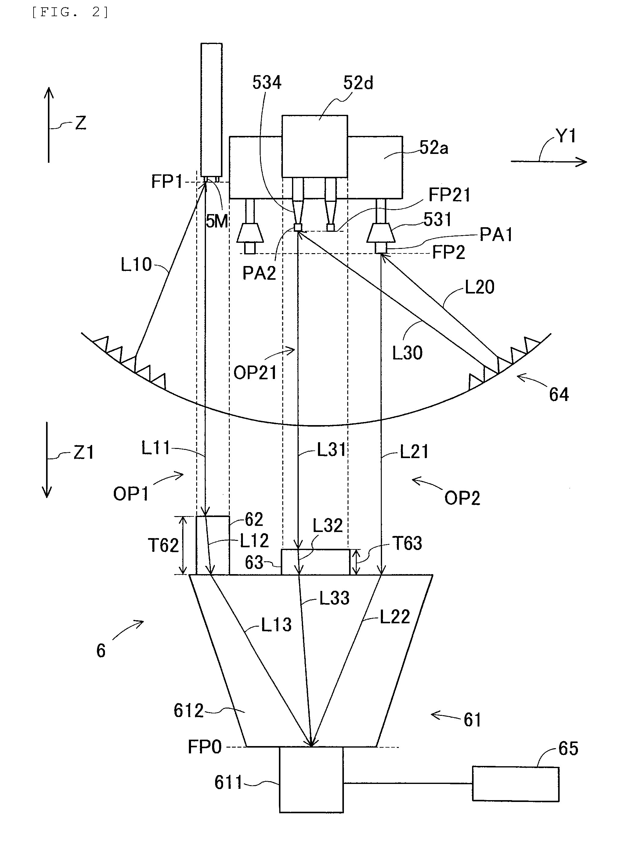
[0017]According to the component-mounting machine described in claim 1, the sucked-component position detection device includes the first refraction member which alters the focal position of the first optical path that connects the image sensor, the lens and the imaging reference mark. Therefore, it is possible to alter the focal position of the first optical path with respect to the imaging reference mark arranged at a height different from that of the sucked component, and to focus on both the imaging reference mark and the sucked component. Moreover, since the first refraction member is provided at a position lower than the focal position of the second optical path that connects the image sensor, the lens and the sucked component, the first refraction member and the sucked component do not collide with each other when the component-mounting head moves to capture images. Therefore, it is not necessary to provide a mechanism for preventing collision of the first refraction member with the sucked component, thereby downsizing the sucked-component position detection device. Moreover, since the first refraction member is provided on the base side of the component-mounting machine, a configuration of the component-mounting head can be further simplified as compared with a case in which the first refraction member is provided on the component-mounting head side, thereby lightening the component-mounting head.
[0018]According to the component-mounting machine described in claim 2, since the second refraction member is provided to alter the focal position of the second optical path, it is possible to alter the focal position of the second optical path in accordance with a height of the sucked component. Moreover, since the second refraction member is provided on the base side and at a position lower than the focal position of the second optical path, it is possible to obtain a similar effect

Problems solved by technology

However, if the aperture is opened, the camera has a shallow depth of field, and thus

Method used


Image

  • Component-mounting machine
  • Component-mounting machine
  • Component-mounting machine

Examples


Embodiment Construction

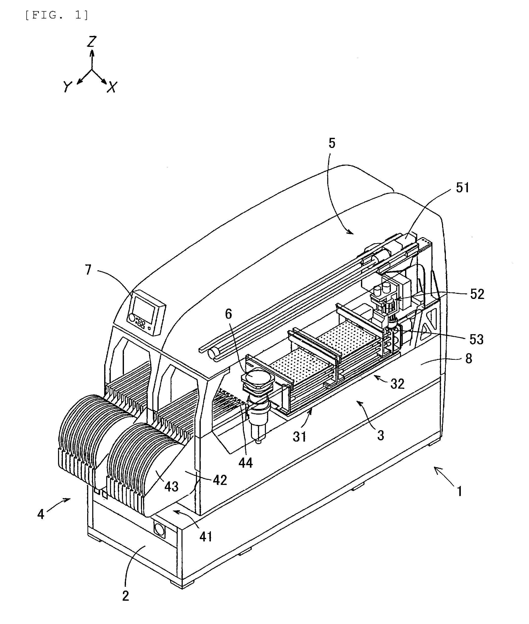
[0025]Hereinafter, embodiments of the present invention will be described based on accompanying drawings. Each diagram is a conceptual diagram, and does not define the size of detailed structures.

(1) Component-Mounting Machine

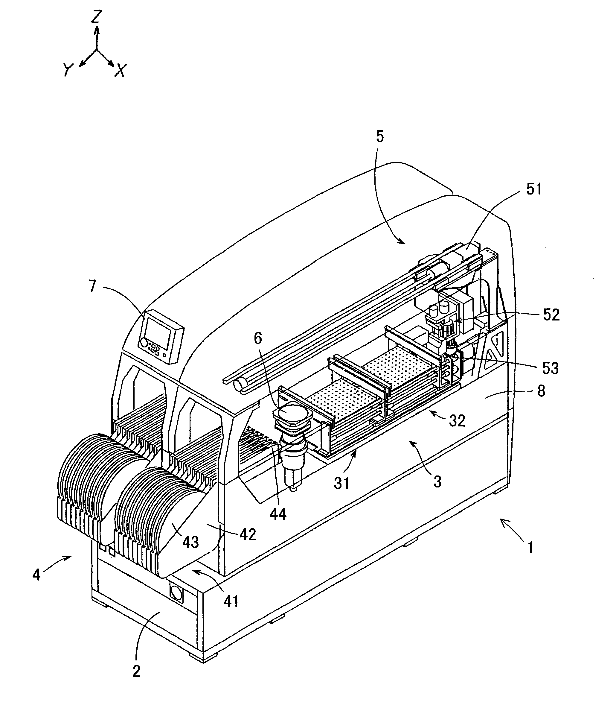
[0026]FIG. 1 is a perspective view expressing an example of the component-mounting machine. In FIG. 1, a conveying direction of the substrate is a traverse direction (indicated by arrow X), and a direction perpendicular to the traverse direction (indicated by arrow X) within a horizontal plane is a longitudinal direction (indicated by arrow Y). Moreover, a normal direction of the horizontal plane is a height direction (indicated by arrow Z). The component-mounting machine 1 includes a substrate conveying device 3, a component feeding device 4, a component transfer device 5, a sucked-component position detection device 6 and a control device 7, which are mounted on a base 8. The base 8 is movably loaded in the longitudinal direction (indicated by arrow Y) with r...


PUM


Abstract

A component-mounting machine which prevents collision of a sucked component with an optical system capturing images of an imaging reference mark and the sucked component simultaneously when a component-mounting head moves to capture images. A sucked-component position detection device includes an imaging unit, which is installed on a side of a base of the component-mounting machine and has an image sensor and a lens; and a first refraction member which alters a first focal position of a first optical path that connects the image sensor, the lens and the imaging reference mark. The first refraction member is installed on the side of the base and at a position lower than a second focal position of a second optical path that connects the image sensor, the lens and the sucked component.

Description

TECHNICAL FIELD[0001]The present invention relates to a component-mounting machine which is able to capture images of an imaging reference mark provided on a component-mounting head and a component sucked by a suction nozzle simultaneously to detect a position of the sucked component with respect to the imaging reference mark.BACKGROUND ART[0002]A component-mounting machine captures images of an imaging reference mark provided on a component-mounting head and a sucked component simultaneously, and detects positional displacement or angle deviation of the sucked component from the captured image. The component-mounting machine further corrects a mounting position of the sucked component based on a detected result, such as the positional displacement and the angle deviation.[0003]Moreover, in the component-mounting machine, the component-mounting head is designed to move at a high speed in order to shorten the time needed for mounting components. When the component-mounting head moves...

Claims


Application Information

Patent Timeline
IPC IPC(8): H04N5/225G02B13/00
CPCH05K13/0413H04N5/2254G02B13/0015H05K13/0812H04N23/55
Inventor YAMAKAGE, YUSUKEYOSHINO, TOMOHARU
Owner FUJI MASCH MFG CO LTD
Learn More