
Pressure differential relief valve

a technology of pressure differential and valve body, which is applied in the direction of functional valve types, water supply installation, transportation and packaging, etc., can solve the problems of excessive pressure or vacuum level in the fluid system, damage to the reservoir or another fluid system component, and the pressure differential between the ambient air and the interior of the reservoir can become greater than

Active Publication Date: 2015-08-06
TERUMO CARDIOVASCULAR SYST CORP
View PDF10 Cites 6 Cited by
  • Summary
  • Abstract
  • Description
  • Claims
  • Application Information

AI Technical Summary

Benefits of technology

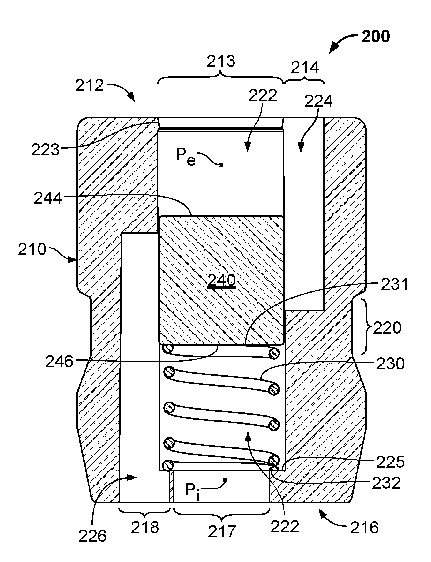
The pressure differential relief valve described in this patent can help prevent damage to fluid systems by reducing pressure differences between the interior and exterior of a reservoir. It can also help equalize both positive and negative pressure differences. When used in a medical context, it can prevent harm to patients. The valve is low-cost and can be used for one-time-use medical fluid reservoirs. The level of differential pressure at which the valve activates to relieve pressure differences can be adjusted, and the negative and positive differential pressures at which the valve activates can be independently established.

Problems solved by technology

However, in some circumstances the pressure differential between the ambient air and the interior of a reservoir can become greater than intended, and undesirable consequences can result.
Such undesirable consequences may include deviating from being in a state of control of the fluid flow, excessive pressure or vacuum levels within the fluid system, damage to the reservoir or another fluid system component, and the like.
In some cases, excessive differential pressures can result in undesirable consequences that may damage the medical fluid system.
Further, in some such circumstances the undesirable consequences can be risky or inherently detrimental to the health of a patient undergoing treatment using the medical fluid system.
Third, when used in a medical context, some embodiments of the pressure differential relief valves provided herein may prevent harm to a patient that is undergoing treatment using a medical fluid system.

Method used


Image

  • Pressure differential relief valve
  • Pressure differential relief valve
  • Pressure differential relief valve

Examples


Embodiment Construction

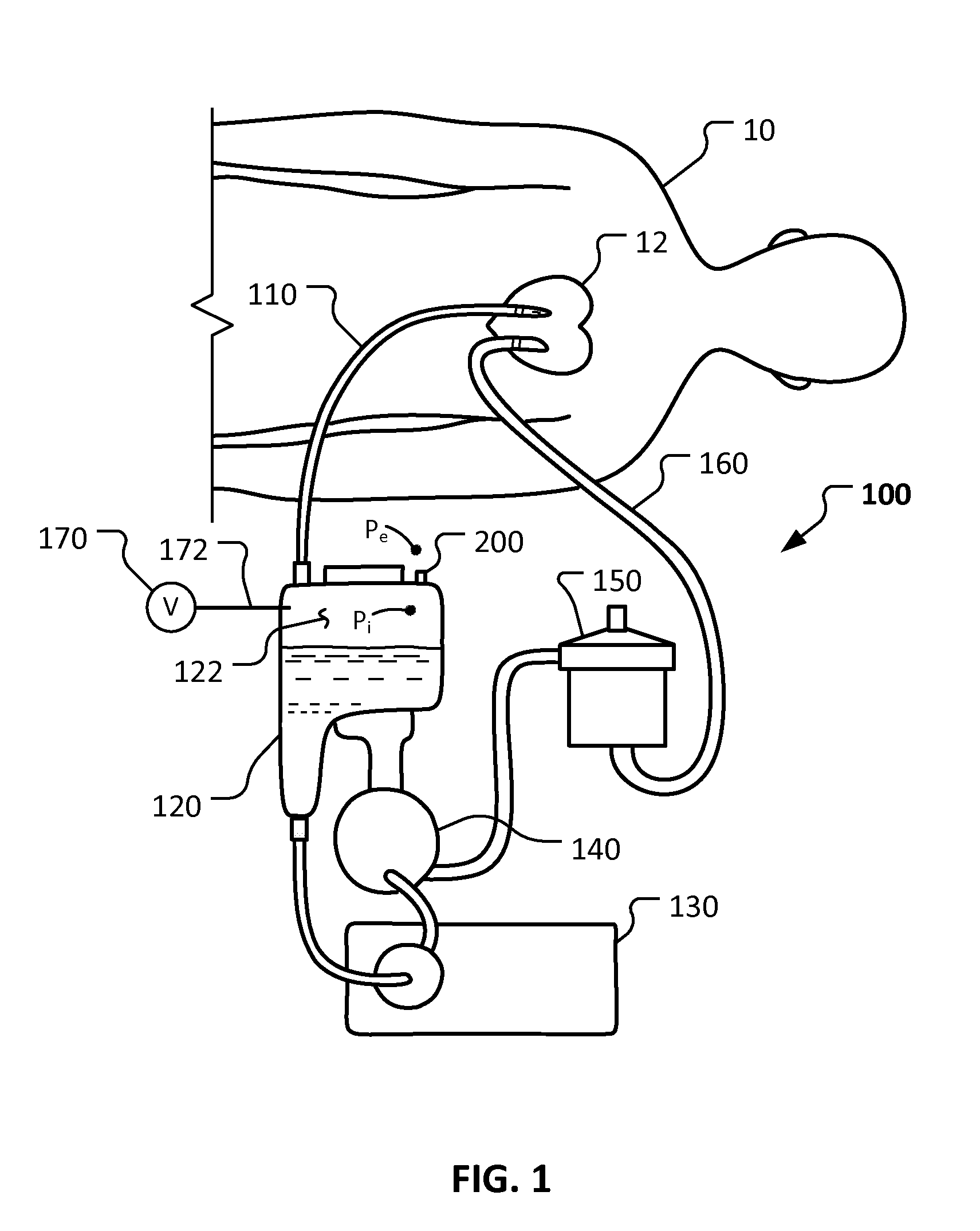
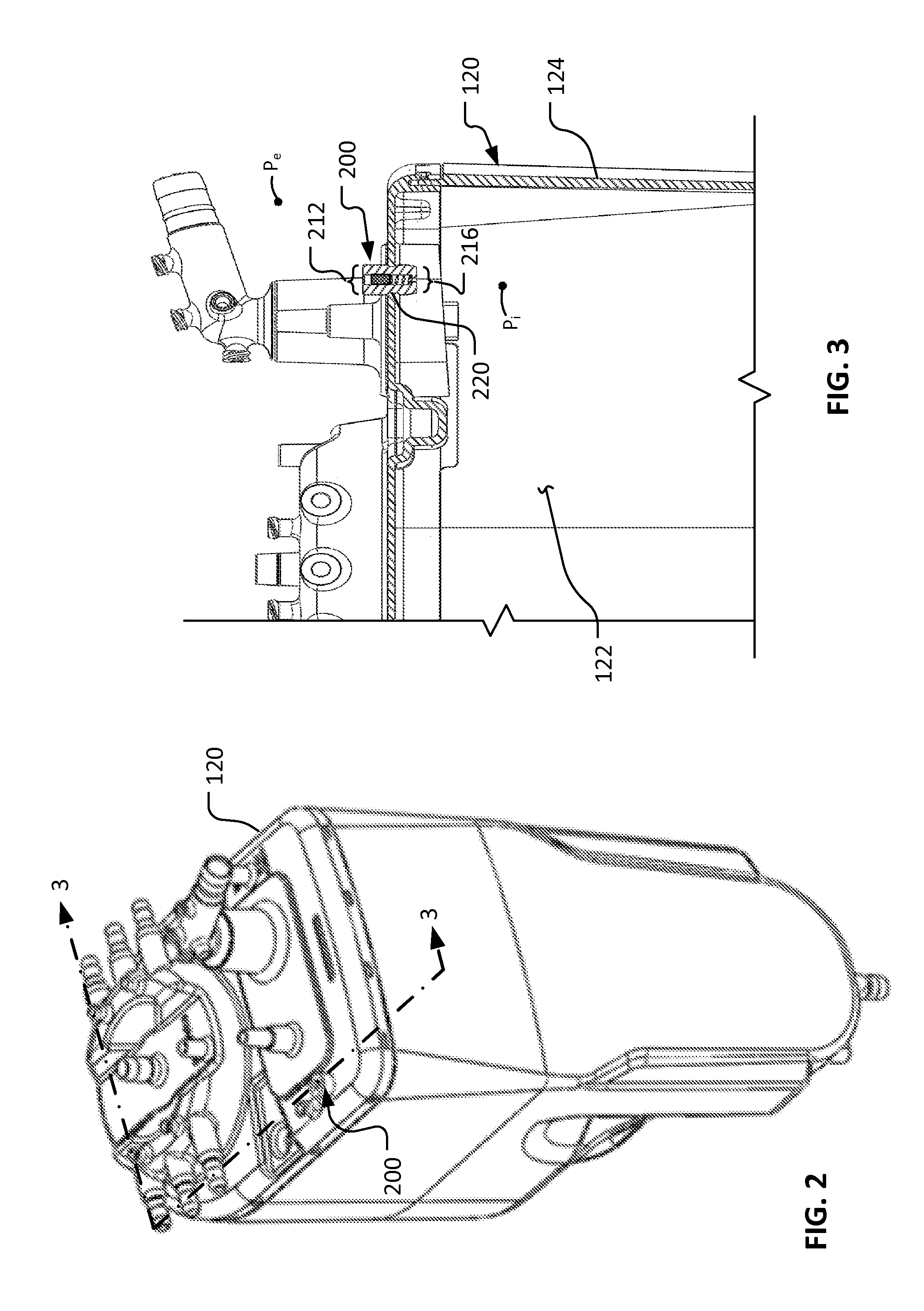
[0034]This document provides devices and methods for enhancing the operations of fluid systems. For example, this document provides pressure differential relief valves that are well suited for use with medical fluid reservoirs. While the pressure differential relief valves provided herein are described in the context of a medical fluid system, such as an extracorporeal blood flow circuit, it should be understood that the devices and methods provided herein are not limited to such contexts. Indeed, the pressure differential relief valves and methods provided herein can be implemented in other types of fluid systems including, but not limited to, pneumatic systems, hydraulic systems, fluid power systems, petroleum systems, and various other types of gaseous or liquid-based fluid systems.

[0035]Referring to FIG. 1, a patient 10 can receive a medical treatment while using a medical fluid system 100. In this illustrative example, the patient 10 is undergoing a heart bypass procedure using...


PUM


Abstract

Devices and methods for enhancing the operations of fluid systems are provided. For example, this document provides pressure differential relief valves that are well suited for use with medical fluid reservoirs. The pressure differential relief valves provided herein are described in the context of a medical fluid system, such as an extracorporeal blood flow circuit, but the devices and methods provided herein can be implemented in other types of fluid systems including, but not limited to, pneumatic systems, hydraulic systems, fluid power systems, petroleum systems, and various other types of gaseous or liquid-based fluid systems.

Description

BACKGROUND[0001]1. Technical Field[0002]This document relates to devices and methods for enhancing the operations of fluid systems. For example, this document relates to pressure differential relief valves that are well suited for use with medical fluid reservoirs.[0003]2. Background Information[0004]Fluid systems commonly include components such as tubing, pumps, reservoirs, heat exchangers, sensors, filters, valves, and the like. Such components can be connected together in a network to define a fluid flow path. Some fluid systems are open systems, meaning that the fluid flows through the network once and then exits the network. Other fluid systems are closed systems, meaning that the fluid recirculates within the network of components. Fluids are caused to flow in the fluid system using fluid pressure differentials. In some cases, a pump is used to create a pressure differential that causes the fluid to flow within the fluid system. In some cases, a vacuum source is used to creat...

Claims


Application Information

Patent Timeline
Patent Type & Authority Applications(United States)
IPC IPC(8): F16K17/196A61M39/24
CPCF16K17/196A61M2039/2493A61M39/24Y10T137/0379Y10T137/7773
Inventor MUENNICH, GREGORY PETER
Owner TERUMO CARDIOVASCULAR SYST CORP
Learn More