
Fire protection device and method for fire protection of an industrial oil cooker

a technology for fire protection devices and oil cookers, applied in the field of fire suppression devices, can solve the problems of insufficient structural configuration of these nozzles, failure to address industrial oil cookers, and fire protection systems

Inactive Publication Date: 2015-08-06
TYCO FIRE PRODS LP
View PDF12 Cites 3 Cited by
  • Summary
  • Abstract
  • Description
  • Claims
  • Application Information

AI Technical Summary

Benefits of technology

[0005]Preferred embodiments of a fire protection nozzle for industrial oil cookers, oil cookers with a fire protection system, and methods of oil cooker fire protection are provided. The preferred embodiments of a mist nozzle operate at pressures preferably between 170 and 250 psi, and provide a unique distribution pattern that allows for variable installations for protection in certain operative environments such as industrial oil fryers.

Problems solved by technology

Due to the failure of the '165 patent to specify an appropriate mist pattern for addressing a fire in the oil of an industrial oil cooker, the fire protection system of the '165 patent fails to address industrial oil cookers that have their hood surface in a fixed positions with respect to the oil surface, e.g., regardless if the hood surface is parallel to the oil surface or angled to the oil surface.
While various mist nozzles are known in the art that operate in the pressure ranges specified by the '165 patent; the inventors have discovered that the structural configuration of these nozzles is insufficient to provide a spray pattern that addresses the deficiency of the fire protection system of the '165 patent with a nozzle having a minimum operating pressure to be considered a low or medium pressure system.

Method used


Image

  • Fire protection device and method for fire protection of an industrial oil cooker
  • Fire protection device and method for fire protection of an industrial oil cooker
  • Fire protection device and method for fire protection of an industrial oil cooker

Examples


Embodiment Construction

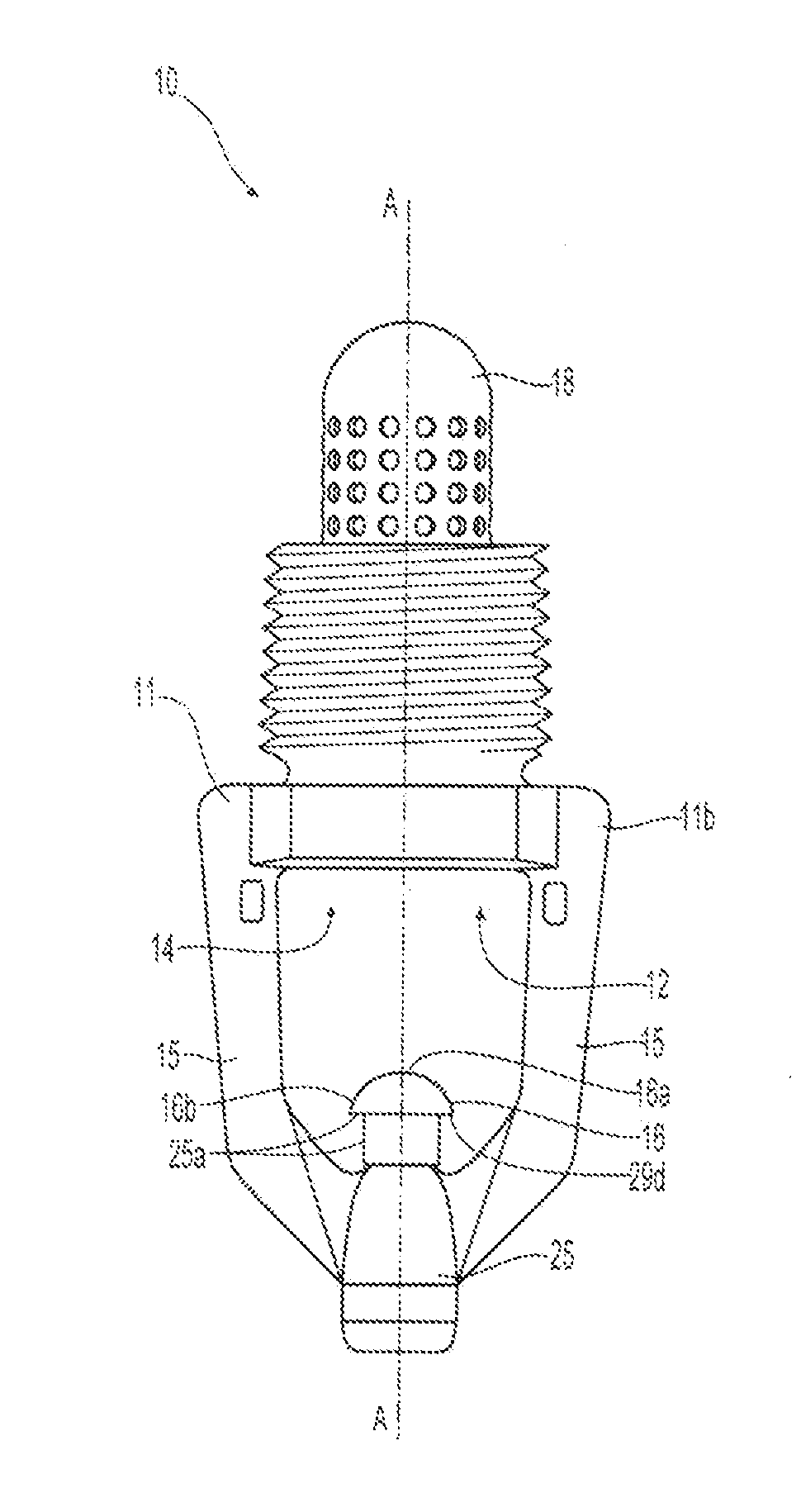
[0021]Referring to FIGS. 1 and 2, the invention provides a fire protection nozzle 10 having a base 11 with a passage 12 through which a fire-fighting fluid is delivered to a protected or coverage area. The passage 12 extends along a central axis A-A between an upstream inlet 13 of the nozzle that connects to a fire-fighting fluid supply system and a downstream outlet 14 of the nozzle that delivers the fluid to the coverage area. The base has arms 15 that extend downstream where they converge to provide support for a diffuser 16 positioned to receive a flow of the fluid exiting the outlet 14 to disperse the flow in a dispersal pattern to the coverage area. The passage 12 includes an orifice 17 that controls the delivery of the fluid through the passage, preferably providing a K-factor of less than 1.0 gpm / psi½ and, more preferably, providing a K-factor of about 0.3 gpm / psi½. As used herein, the K-factor is defined as a constant representing the sprinkler discharge coefficient, that i...


PUM


Abstract

Fire protection mist nozzles for industrial oil cookers, oil cookers with fire protection systems, and method of oil cooker fire protection are provided. The mist nozzles operate at pressures between 170 and 250 psi, and provide a unique distribution pattern that allows for variable installations for protection in certain operative environments including oil cookers with various hood configurations. The fire protection nozzles includes a base defining an inlet and an outlet along an axis. The base includes an orifice having an inlet diameter and an outlet diameter. The outlet diameter is preferably greater than the inlet diameter; and the orifice defines a K-factor of less than 1.0 gpm / psi½. The nozzle includes a diffuser aligned with the orifice. The diffuser has a preferably substantially domed portion with a maximum diameter that is less than the summation of the inlet diameter and the outlet diameter of the orifice.

Description

CROSS REFERENCE TO RELATED APPLICATIONS[0001]This international application claims the benefit of priority to U.S. Provisional Application No. 61 / 801,384, filed Mar. 15, 2013, which is incorporated herein by reference in its entirety.FIELD OF INVENTION[0002]This invention relates generally to fire suppression devices such as water mist nozzles, and methods of installing such nozzles for protection from fires. More specifically, the invention is directed to fire suppression nozzles and methods for the suppression of fires in industrial oil cookers or otherwise known as industrial oil fryers.BACKGROUND OF THE INVENTION[0003]A fire protection system for an industrial oil cooker is shown and described in U.S. Pat. No. 7,789,165. The '165 patent provides an oil cooker that has a longitudinally elongated cooker pan, a longitudinally elongated hood directly above the pan; and mist producing nozzles that are piped and disposed beneath the top wall of the hood and above the pan of oil. To as...

Claims


Application Information

Patent Timeline
Patent Type & Authority Applications(United States)
IPC IPC(8): A62C3/00A47J37/12
CPCA47J37/1276A62C3/006A62C31/02A62C99/0072A62C31/005B05B1/265A47J37/1271
Inventor MAGNONE, ZACHARY L.ALMEIDA, JOSE L.BOWDER, JR., THOMAS W.GOYETTE, CHAD A.
Owner TYCO FIRE PRODS LP
Learn More