
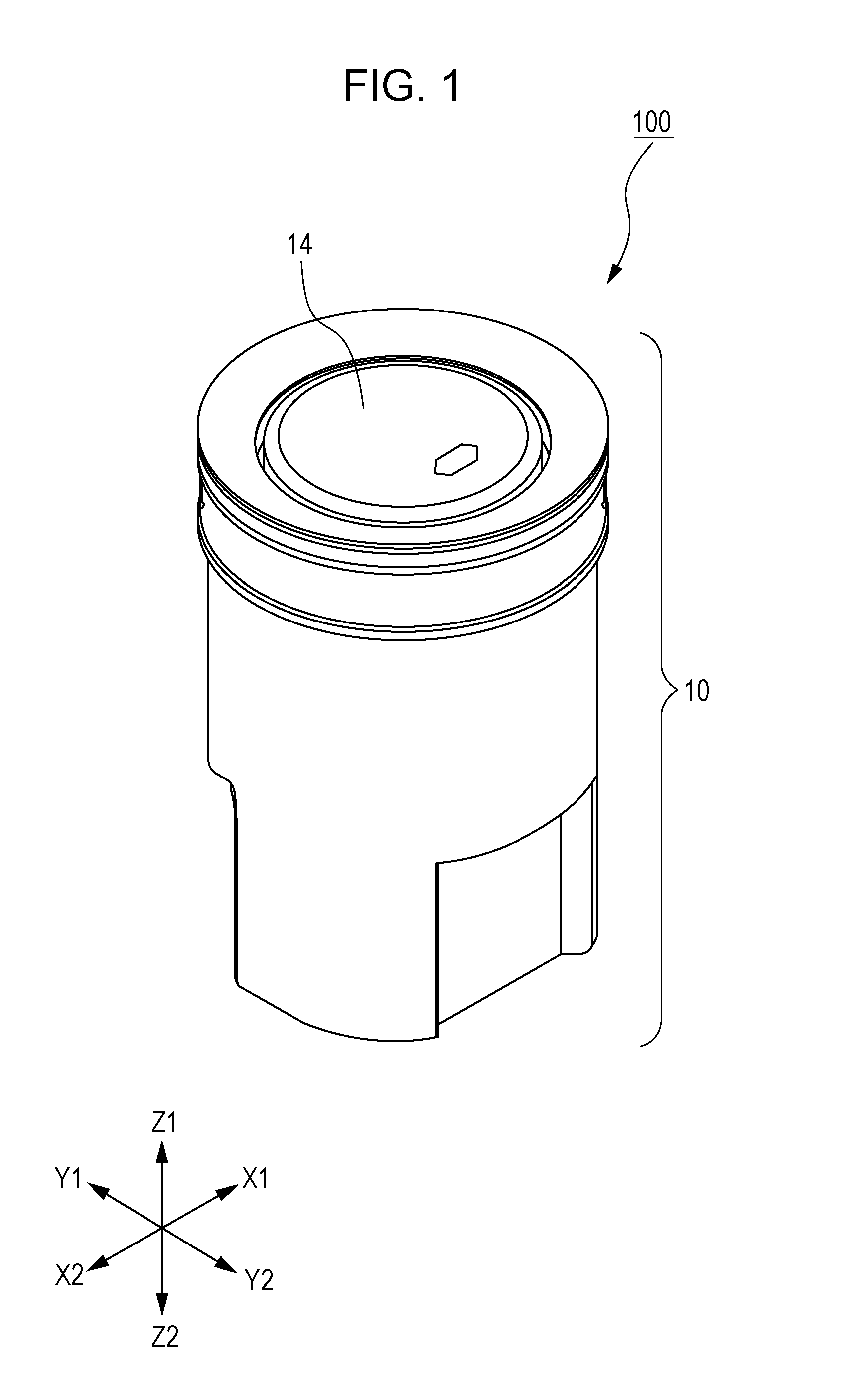
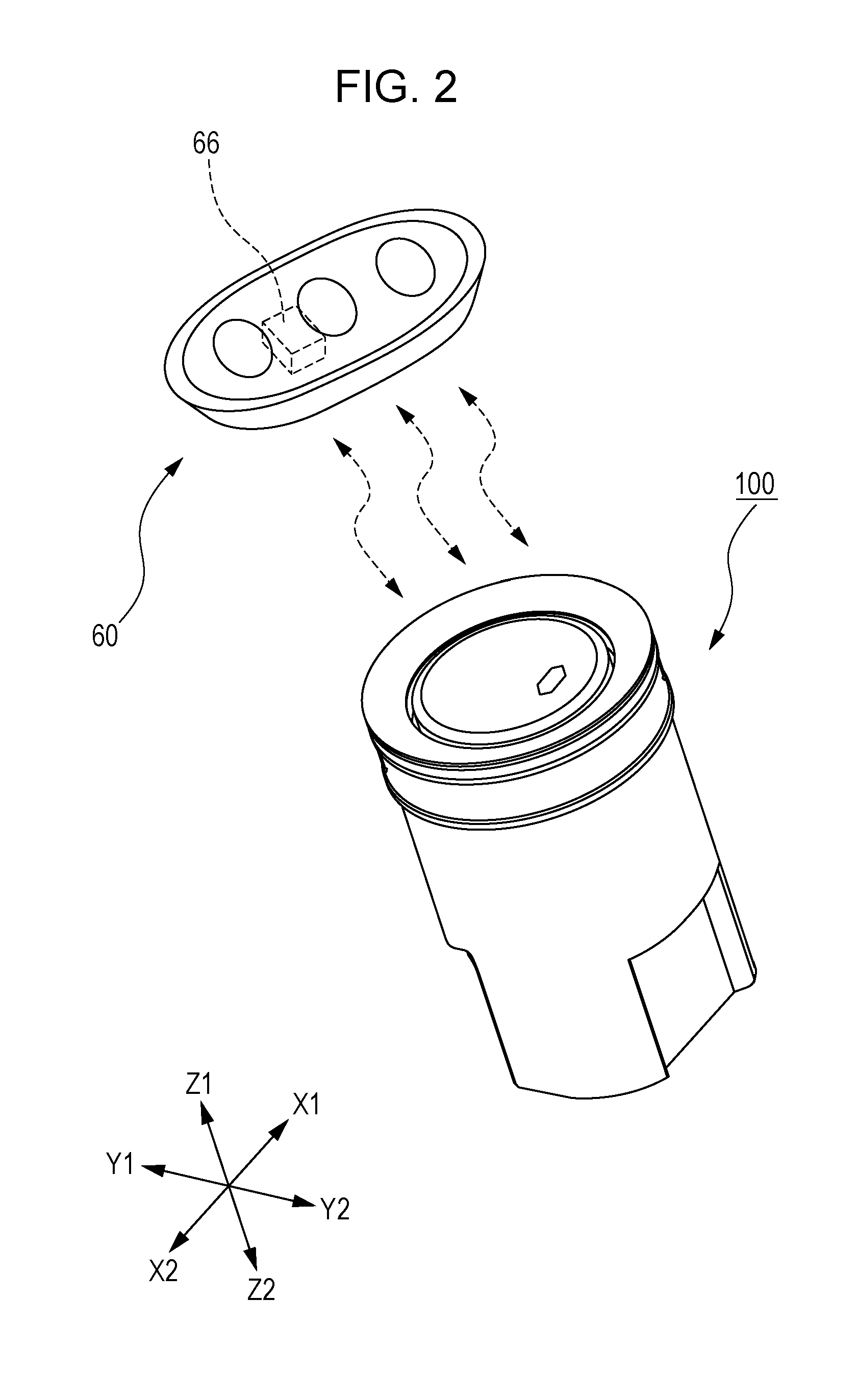
Push-button switch

Active Publication Date: 2015-07-30
ALPS ALPINE CO LTD
View PDF3 Cites 7 Cited by
  • Summary
  • Abstract
  • Description
  • Claims
  • Application Information

AI Technical Summary

Benefits of technology

The push-button switch described in this patent has a coil antenna that can communicate with a portable device even when it is attached to the bottom of a circuit board. The direction of current flow in the coil conductor matches the direction of current flow in the conductor pattern, which helps to achieve a long communication distance. The switch also has a high-intensity magnetic field that overlaps with the conductor pattern, further increasing the communication distance. The conductor pattern is composed of two spiral-shaped patterns connected in a way that ensures the direction of current flow is the same as the direction of current flow in the coil conductor.

Problems solved by technology

If the remaining battery level of the portable device becomes equal to or lower than a predetermined value, communication between the main body of an automobile and the portable device may fail to be performed.
However, when the coil antenna having a loop portion wound around the magnetic member, as described in U.S. Patent Application Publication No. 2012 / 0119965, is applied to a transmission / reception antenna in a push-button switch for engine start which is used in an immobilizer system in a vehicle, there arises the following problem.
However, when the coil antenna is attached on the bottom surface of the wiring board, the distance from the portable device is long, and communication with the portable device may fail to be performed.

Method used


Image

  • Push-button switch
  • Push-button switch
  • Push-button switch

Examples


Embodiment Construction

[0033]The following description is intended to convey a thorough understanding of the embodiments described by providing a number of specific embodiments and details involving an push button switch. It should be appreciated, however, that the present invention is not limited to these specific embodiments and details, which are exemplary only. It is further understood that one possessing ordinary skill in the art, in light of known systems and methods, would appreciate the use of the invention for its intended purposes and benefits in any number of alternative embodiments, depending on specific design and other needs.

[0034]The example embodiments of the present disclosure will be described below with reference to the drawings. Herein, unless otherwise specified, description will be made by using the X1 side in the drawings as the right, using the X2 side as the left, using the Y1 side as the back side, using the Y2 side as the front side, using the Z1 side as the upper side, and usin...


PUM


Abstract

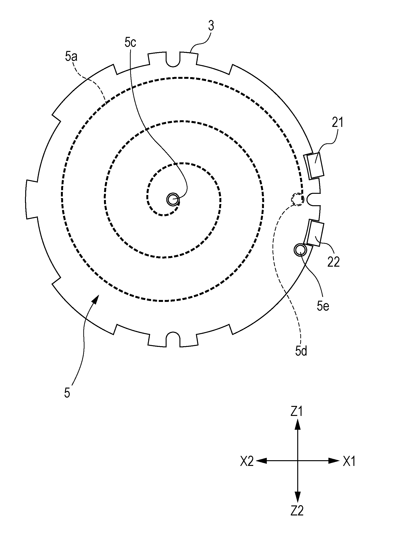
A push-button switch includes a wiring board having a first surface on which electronic components are mounted. The push-button switch is used for an immobilizer system and supplies power to a portable device from the first surface side of the wiring board. The push-button switch includes a coil antenna and a conductor pattern. The coil antenna includes a magnetic core and a coil conductor wound around the magnetic core. The coil antenna is attached to a second surface of the wiring board. The conductor pattern is formed in at least one wiring layer so as to surround the coil conductor in plan view. The wiring board has an inner layer including the at least one wiring layer. A direction of current flowing through the coil conductor is the same as a direction of current flowing through the conductor pattern.

Description

CLAIM OF PRIORITY[0001]This application contains subject matter related to and claims the benefit of Japanese Patent Application No. 2014-014555 filed on Jan. 29, 2014, the entire contents of which is incorporated herein by reference.BACKGROUND OF THE DISCLOSURE[0002]1. Field of the Disclosure[0003]Embodiments of the present disclosure relate to a push-button switch, and particularly to a push-button switch for engine start which is used in an immobilizer system in a vehicle.[0004]2. Description of the Related Art[0005]In moving vehicles, such as automobiles, of the related art, an engine is started by inserting a key into a key hole and operating the key. Recently, a so-called immobilizer system in which an engine is started without inserting a key into a key hole has been used for convenience. The immobilizer system has a configuration having high security in such a manner that an authentication function for engine start is provided and that, when the authentication is not establi...

Claims


Application Information

Patent Timeline
IPC IPC(8): H01Q1/32H01H13/02H01Q1/22
CPCH01Q1/3233H01H2231/026H01H13/023H01Q1/2216H01Q7/08H01H2239/024H01H13/14H01H3/12H01Q7/06H01Q1/3241
Inventor SANO, TAKASHISAGO, TETSUYA
Owner ALPS ALPINE CO LTD
Learn More