
Planar sensor array for non-destructive evaluation of material using electromagnetic impedance

a sensor array and electromagnetic impedance technology, applied in the direction of material impedance, resistance/reactance/impedence, instruments, etc., can solve the problems of limiting the potential depth of evaluation into the mut, the size of the electrode array is not readily conducive to providing tomographic information, and the array also has limitations

Active Publication Date: 2015-07-30
TRANSTECH SYST
View PDF4 Cites 10 Cited by
  • Summary
  • Abstract
  • Description
  • Claims
  • Application Information

AI Technical Summary

Benefits of technology

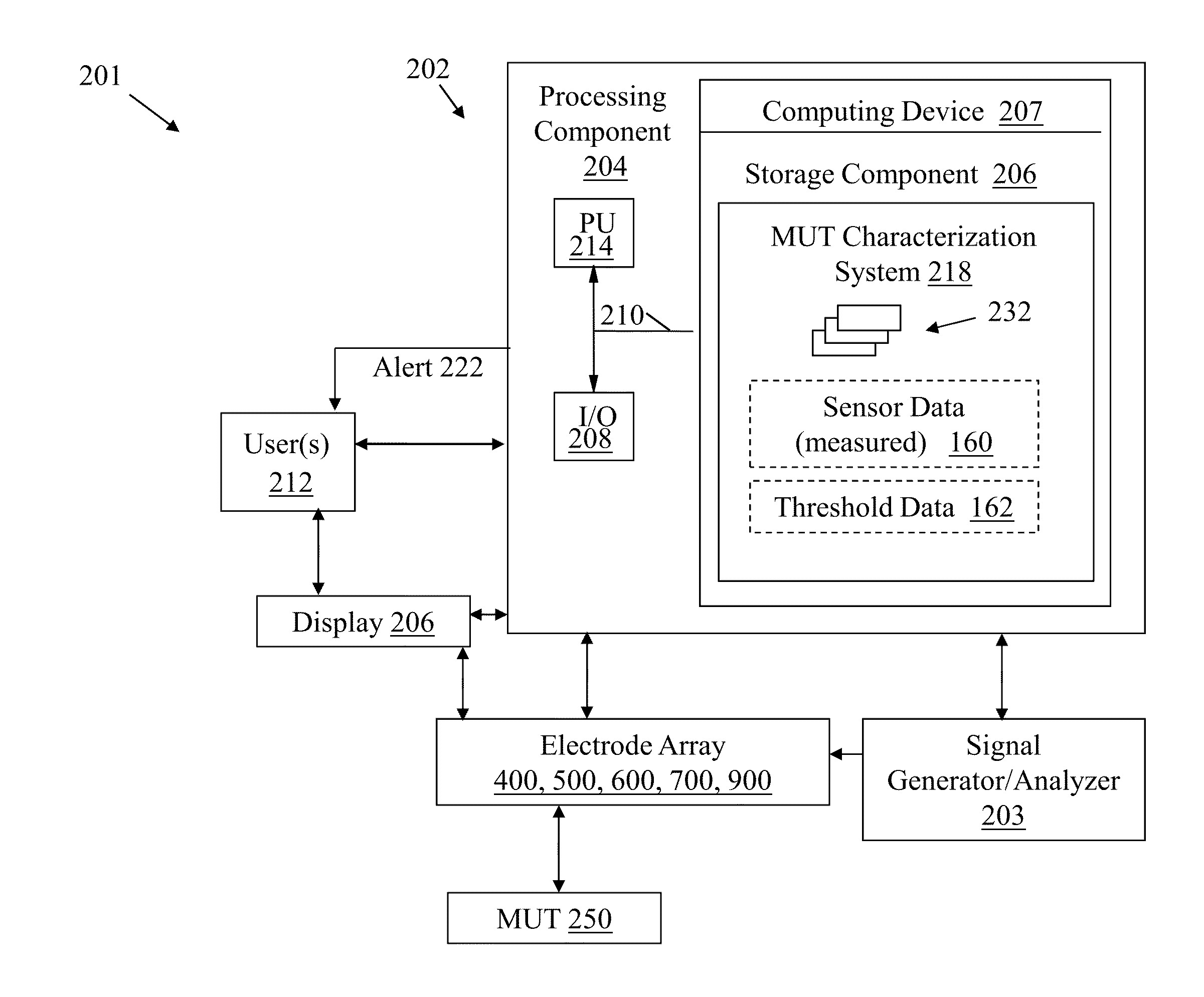
The invention includes systems, apparatuses, and designs to secure the electromagnetic impedance characteristics of a selected volume of one or more materials under test (MUTs) to determine its electromagnetic impedance characteristics and relate them to physical properties of that volume of the MUT. The patent also describes planar sensor arrays for use in determining characteristics of a material under test (MUT) by detecting an electromagnetic impedance. The systems include a signal generator, a signal detector, and a computing device to determine the electromagnetic impedance characteristics and correlate it to physical properties of the MUT. Additionally, the patent describes an electromagnetic sensor array that can detect the electromagnetic impedance of a surface and subsurface of the MUT. The technical effects of this invention include improved accuracy and efficiency in the measurement of electromagnetic impedance and physical properties of MUTs.

Problems solved by technology

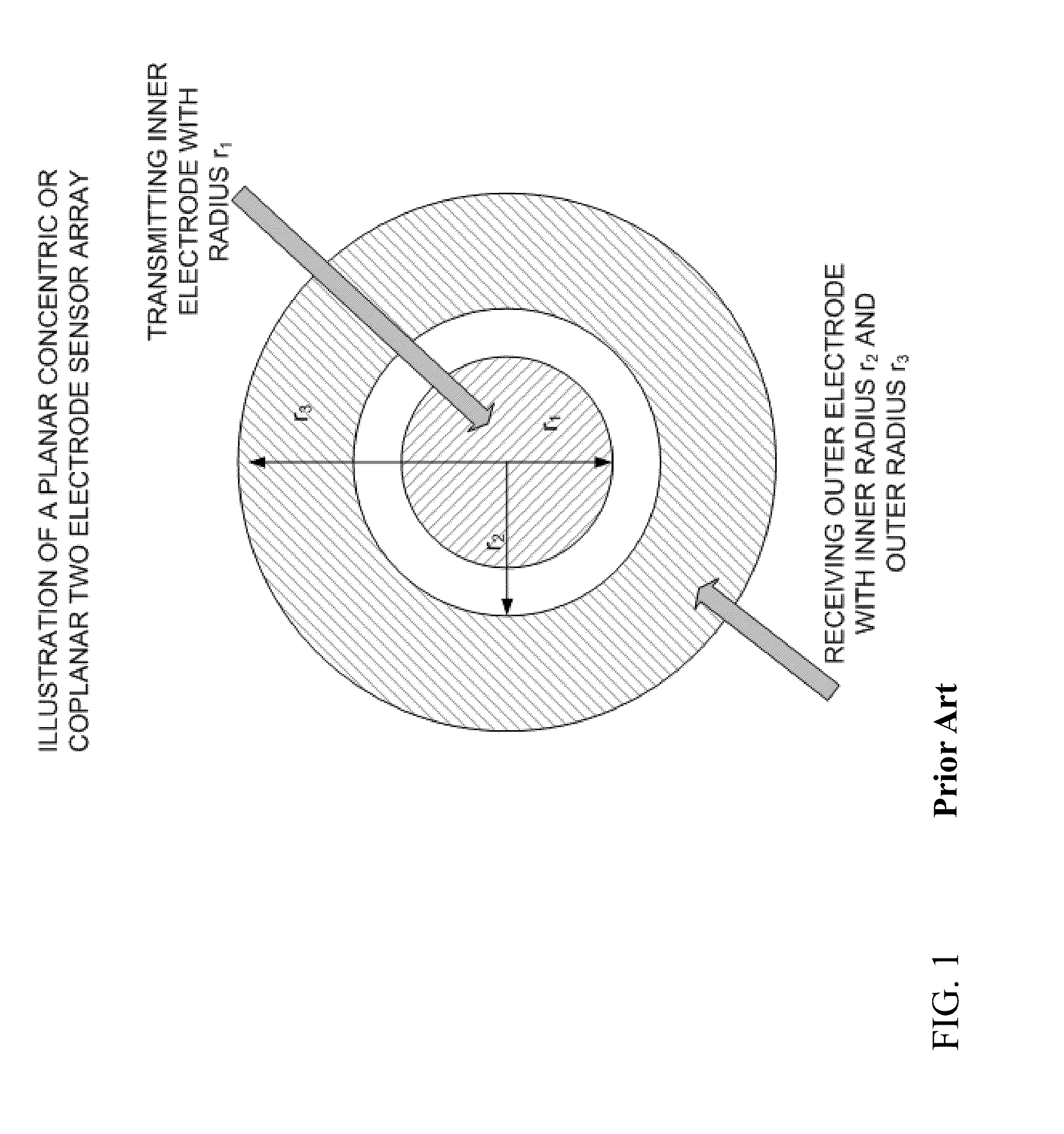
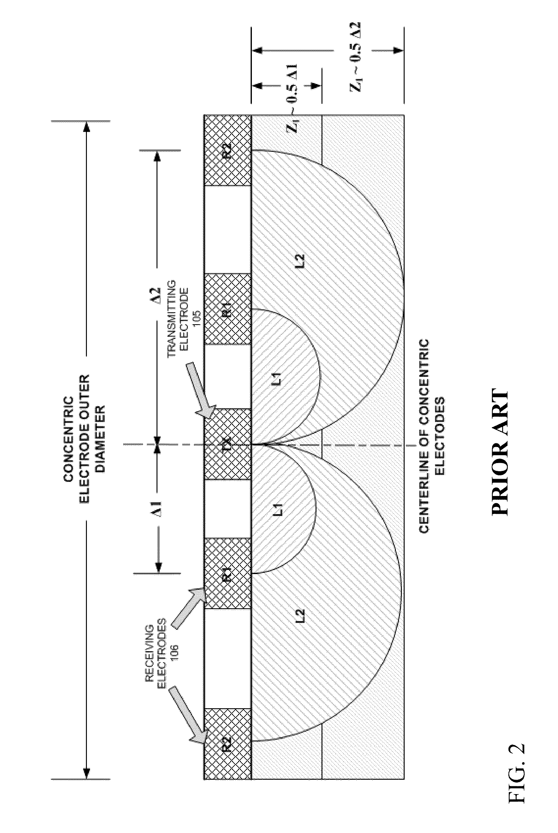
The planar concentric electrode arrays fall under a class of electronics that is termed “coplanar wave guides.” While there are a number of advantages in using the concentric electrode array, this array also has limitations.
A first limitation is that the concentric electrode array is not readily conducive to providing tomographic information.
A second limitation of the concentric electrode array is that the size of the electrode array limits the potential depth of evaluation into the MUT.

Method used


Image

  • Planar sensor array for non-destructive evaluation of material using electromagnetic impedance
  • Planar sensor array for non-destructive evaluation of material using electromagnetic impedance
  • Planar sensor array for non-destructive evaluation of material using electromagnetic impedance

Examples


Embodiment Construction

[0020]The following discussion expands on and improves the methodology disclosed in prior art to measure the impedance in a volume or volumes of the MUT using multiple electrodes arranged on a planar array in non-conducting communication with the MUT.

[0021]U.S. Pat. Nos. 5,900,736, 6,400,161, 6,414,497, and 6,677,763 present a two electrode sensor array as a means to evaluate the density of asphalt using electromagnetic impedance characteristics of the asphalt. The concentric two electrode sensor may also be classified electrically as a coplanar wave guide as noted in Patent Publication No. 2012 / 0013354. This prior art does not use any spectrographic or tomographic approaches but illustrates two electrode geometries for use with electromagnetic impedance measuring devices. U.S. Pat. No. 7,219,021 presents the use of a concentric coplanar electrode array with electromagnetic impedance spectroscopy to evaluate the density and moisture of soils. These electrode arrays are in non-conduc...


PUM

PropertyMeasurementUnit
angleaaaaaaaaaa
electromagnetic impedanceaaaaaaaaaa
shapeaaaaaaaaaa

Abstract

Various embodiments include planar sensor arrays for use in determining characteristics of a material under test (MUT). The planar sensor arrays can include a set of electrodes positioned to enhance a depth and clarity of detection into the material under test. Some embodiments include an electromagnetic sensor array having: a first set of two rectilinear electrodes, positioned opposed to one another across a space; and a second set of two rectilinear electrodes, positioned opposed to one another across the space, the second set being off-set from the first set, wherein the first set and the second set are configured to detect an electromagnetic impedance of the MUT.

Description

CROSS-REFERENCE TO RELATED APPLICATION[0001]This application claims priority to U.S. Provisional Patent Application No. 61 / 932,400, which is hereby incorporated by reference in its entirety.TECHNICAL FIELD[0002]Various embodiments of the invention relate to planar sensor arrays for use with electromagnetic impedance sensors to non-destructively evaluate the physical properties of materials under test (MUT). The designs of the sensor array may enhance the depth of measurement into the MUT within a defined sensor size, and may enhance the signal-to-noise ratio.BACKGROUND[0003]The use of electromagnetic impedance measurement devices to secure physical properties of a material under test with a planar electrode sensor array have been identified in U.S. Pat. Nos. 5,900,736, 6,400,161, 6,414,497, and 7,219,024, each of which is hereby incorporated by reference in its entirety. The apparatus covered in U.S. Pat. Nos. 5,900,736, 6,414,497, and 7,219,024, use a planar concentric electrode ar...

Claims


Application Information

Patent Timeline
Patent Type & Authority Applications(United States)
IPC IPC(8): G01N27/02
CPCG01N27/02
Inventor PLUTA, SARAH E.COLOSIMO, DONALD D.HEWITT, JOHN W.
Owner TRANSTECH SYST
Learn More