
Vehicle driving force distribution device

a technology of driving force and distribution device, which is applied in the direction of gearing details, gearing, transportation and packaging, etc., can solve problems such as power loss, and achieve the effect of improving fuel economy and reducing drag torque in the clutch

Active Publication Date: 2015-07-09
JTEKT CORP
View PDF6 Cites 17 Cited by
  • Summary
  • Abstract
  • Description
  • Claims
  • Application Information

AI Technical Summary

Benefits of technology

The invention provides a device for distributing driving force in a vehicle that can reduce drag torque in a clutch when a vehicle travels in a two-wheel drive mode, which improves fuel economy.

Problems solved by technology

That is, when the four-wheel-drive vehicle travels in the two-wheel drive mode, this drag torque between the clutch plates serves as travel resistance, thereby causing power loss.

Method used


Image

  • Vehicle driving force distribution device
  • Vehicle driving force distribution device
  • Vehicle driving force distribution device

Examples


Embodiment Construction

[0026]An embodiment of the invention will be described with reference to the accompanying drawings.

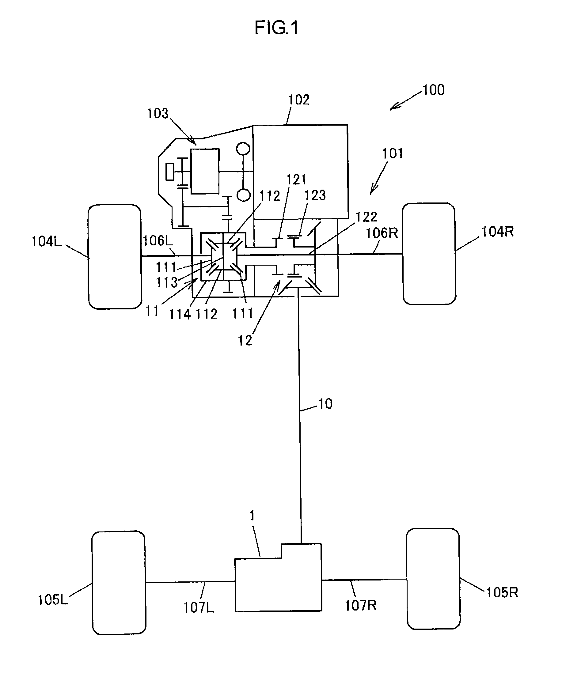
[0027]FIG. 1 is a schematic diagram showing a configuration example of a four-wheel-drive vehicle having mounted thereon a vehicle driving force distribution device according to an embodiment of the invention.

[0028]A four-wheel-drive vehicle 100 includes an engine 102 as a driving source, a transmission 103, a pair of front wheels 104L, 104R as main drive wheels, a pair of rear wheels 105L, 105R as auxiliary drive wheels, and a driving force transmission system 101 that transmits torque of the engine 102 to the pair of front wheels 104L, 104R and the pair of rear wheels 105L, 105R.

[0029]The driving force transmission system 101 has a front differential 11, a dog clutch 12 as an engagement / disengagement mechanism capable of cutting off transmission of a driving force, a propeller shaft 10, a driving force distribution device 1, front drive shafts 106L, 106R, and rear drive shafts 107L, ...


PUM


Abstract

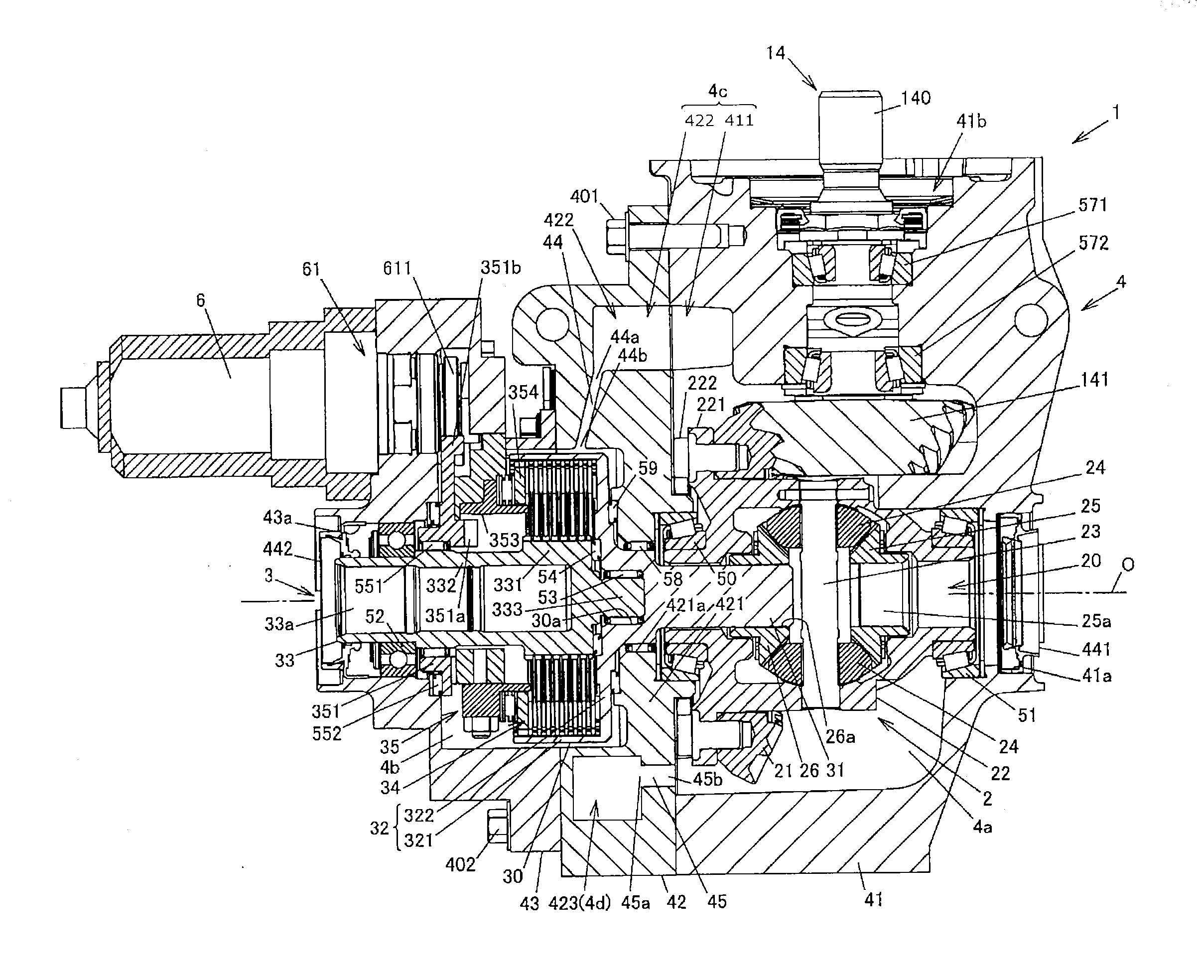
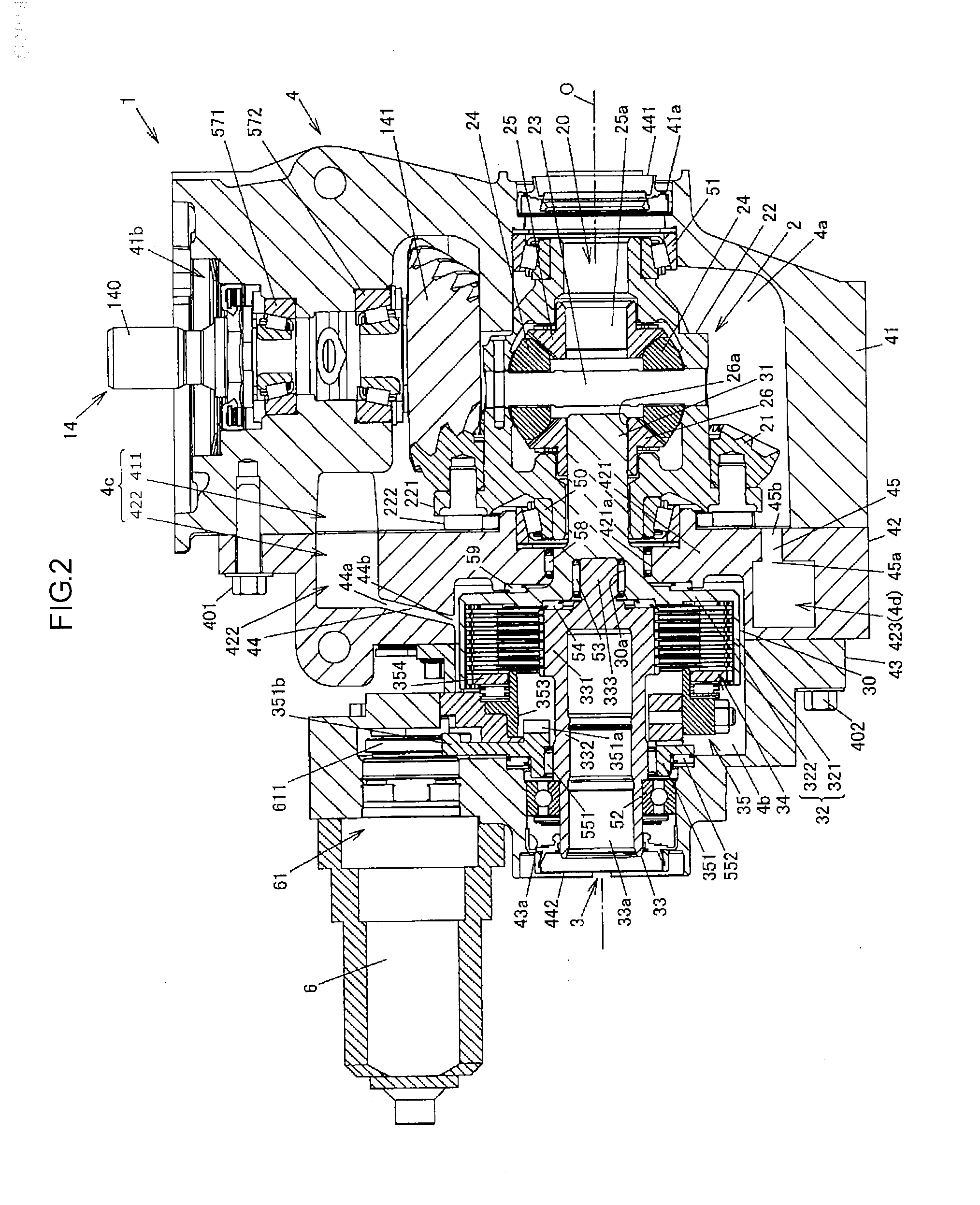
A vehicle driving force distribution device includes: a differential gear; a driving force transmission device; and a case member having a first accommodating chamber accommodating the differential gear and a second accommodating chamber accommodating the driving force transmission device. The case member has a first flow passage that allows lubricating oil to flow from the first accommodating chamber into the second accommodating chamber, and a second flow passage that allows lubricating oil to flow from the second accommodating chamber into the first accommodating chamber. In a two-wheel drive mode, lubricating oil flows from the second accommodating chamber into the first accommodating chamber through the second flow passage. In a four-wheel drive mode, lubricating oil flows from the first accommodating chamber into the second accommodating chamber through the first flow passage.

Description

INCORPORATION BY REFERENCE[0001]The disclosure of Japanese Patent Application No. 2014-000522 filed on Jan. 6, 2014 including the specification, drawings and abstract, is incorporated herein by reference in its entirety.BACKGROUND OF THE INVENTION[0002]1. Field of the Invention[0003]The invention relates to vehicle driving force distribution devices that distribute a driving force received from an input shaft to first and second output shafts.[0004]2. Description of the Related Art[0005]Conventionally, a driving force distribution device is known which is placed on an auxiliary drive wheel-side in a driving force transmission system of a four-wheel-drive vehicle including main drive wheels to which a driving force of a driving source is constantly transmitted and auxiliary drive wheels to which the driving force of the driving source is transmitted according to the traveling state, and which distributes the driving force received from a propeller shaft to right and left wheels. See,...

Claims


Application Information

Patent Timeline
Patent Type & Authority Applications(United States)
IPC IPC(8): F16H57/04B60K17/346F16H48/38
CPCF16H57/0424B60K17/346F16H48/38B60K17/35F16H57/0473F16H57/0483
Inventor SUZUKI, KUNIHIKO
Owner JTEKT CORP
Learn More