Crash cushion

a cushion and crash technology, applied in roadway safety arrangements, roads, construction, etc., can solve the problems of limiting the ability to deploy the system and adding to the overall cost of the system, and achieve the effects of shortening the footprint, absorbing a greater amount of energy, and being convenient to us

Active Publication Date: 2015-07-09
ENERGY ABSORPTION SYST
View PDF6 Cites 1 Cited by
  • Summary
  • Abstract
  • Description
  • Claims
  • Application Information

AI Technical Summary

Benefits of technology

[0008]The various embodiments of the crash cushion, and the methods for the use and assembly thereof, provide significant advantages over other crash cushions. For example and without limitation, the crash cushion may be made shorter and more compact while the capacity to meet crash test standards defined under NCHRP-350. In this way, the crash cushion may be deployed in various situations requiring a relatively short footprint. Conversely, a crash cushion of the same length may be constructed to absorb a greater amount of energy. In either case, the crash cushion may be made at a reduced cost, with less materials, greater portability and easier reconfigurability after a crash. For example and without limitation, the use of segments allows for the increased energy absorption of individual cylinders, or tubes, thereby yielding an opportunity to absorb greater energy per unit weight of material. At the same time, the tube may be made of a thinner material, which undergoes less strain at the outer circumferential portions thereof (i.e., outer fibers), which correlates to less permanent deformation.
[0009]In addition, the segments provide for an inexpensive and easy way to “tune” the crash cushion for various energy absorbing scenarios. Segments of different thicknesses, lengths (circumferential) and heights (axial length) may be selected depending on the desired cost efficiency, amount of energy to be absorbed, or the shape of the force / deflection curve. Likewise, the number and types of openings, and fastening devices, may be altered to provide different energy absorbing characteristics.

Problems solved by technology

These parameters may add to the overall cost of the system, and / or may limit the ability to deploy the system in certain environments having various spatial constraints.

Method used


Image

  • Crash cushion
  • Crash cushion
  • Crash cushion

Examples


Embodiment Construction

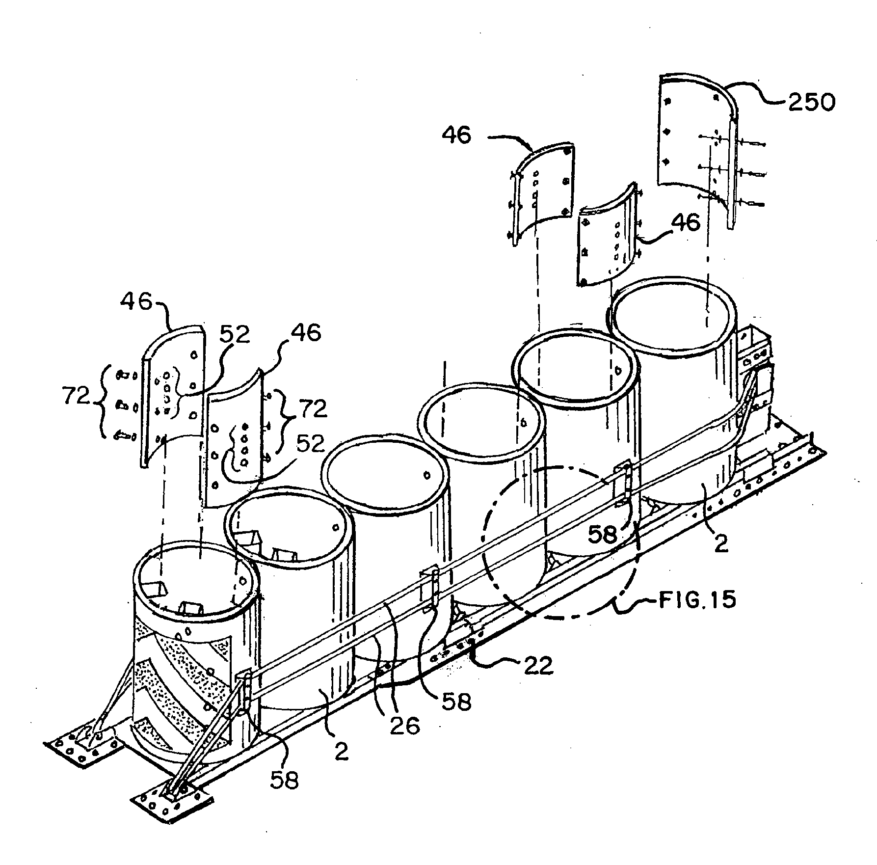
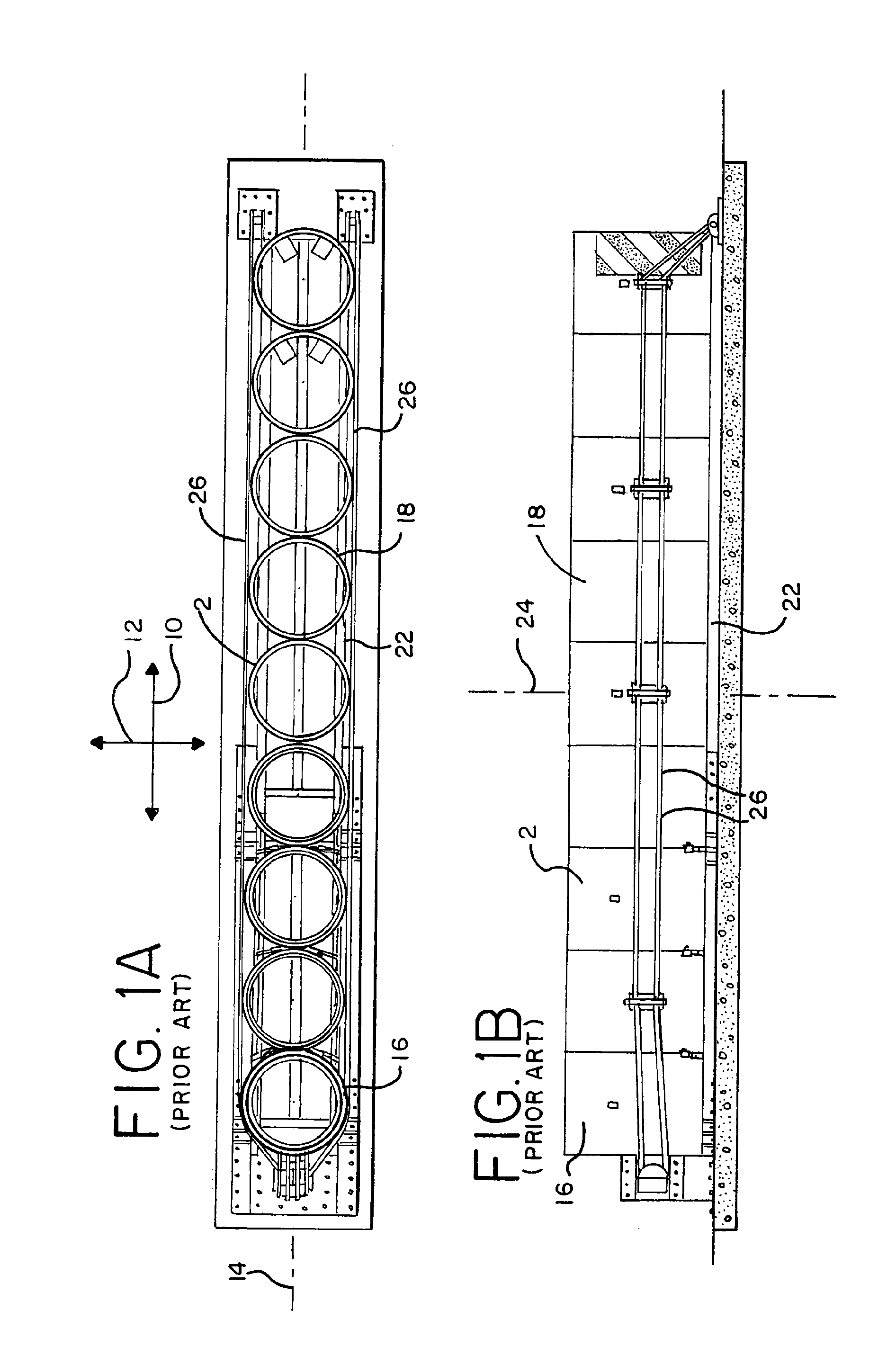
[0029]It should be understood that the term “plurality,” as used herein, means two or more. The term “longitudinal,” as used herein means of or relating to length or the lengthwise direction 10 of the crash cushion, or assembly thereof. The term “lateral,” as used herein, means directed between or toward (or perpendicular to) the side of the crash cushion, for example the lateral direction 12, further defined below. The term “coupled” means connected to or engaged with, whether directly or indirectly, for example with an intervening member, and does not require the engagement to be fixed or permanent, although it may be fixed or permanent. The term “transverse” means extending across an axis, and / or substantially perpendicular to an axis. It should be understood that the use of numerical terms “first,”“second,”“third,” etc., as used herein does not refer to any particular sequence or order of components; for example “first” and “second” connector segments may refer to any sequence o...


PUM


Abstract

A crash cushion includes a plurality of resilient, self-restoring tubes each having a center axis and an interior surface. At least some of the tubes are positioned such that respective ones of the center axes are spaced apart in a longitudinal direction. The center axis of at least one tube is substantially perpendicular to a longitudinal axis extending in the longitudinal direction, with the tube defining a diametral plane intersecting and oriented substantially perpendicular to the longitudinal axis. The center axis of the tube lies in the diametral plane. One or more segments are positioned in the tube, with the segments, or portions thereof, disposed on opposite sides of the interior surface of the tube. Each of the segments or portions is symmetrically secured to the tube relative to the diametral plane, with the tube being substantially open between the opposing segments. Various methods of using and assembling the crash cushion are also provided.

Description

[0001]This application is a continuation of U.S. application Ser. No. 13 / 290,550, filed Nov. 7, 2011, which application claims the benefit of U.S. Provisional Application 61 / 413,798, filed Nov. 15, 2010, the entire disclosures of which are hereby incorporated herein by reference.FIELD OF THE INVENTION[0002]The present invention relates generally to a crash cushion, and in particular, to a crash cushion configured with at least one tube reinforced with a resilient segment.BACKGROUND[0003]Crash cushions may be used alongside highways in front of obstructions such as concrete walls, toll booths, tunnel entrances, bridges and the like so as to protect the drivers of errant vehicles. Various types of crash cushions may be configured with a plurality of energy absorbing elements, such as an array of resilient, self-restoring tubes, which facilitate the ability to reuse the crash cushion after an impact. The tubes 2 may be exposed, as configured for example in the REACT 350® impact attenua...

Claims


Application Information

Patent Timeline
Patent Type & Authority Applications(United States)
IPC IPC(8): E01F15/08
CPCE01F15/086E01F15/088E01F15/08E01F15/146
Inventor BUEHLER, MICHAEL J.COX, AARON J.
Owner ENERGY ABSORPTION SYST
Why Eureka
Try Eureka