
Mechanism for securing a balance spring stud to a balance bridge and sprung balance regulating device including such a mechanism

a technology of a balance spring and a regulating device, which is applied in the direction of frequency setting mechanism, instruments, and significant chronometric defects, which can solve the problems of difficult adjustment of inability to adjust the position of the stud, and inability to adjust the stud by plastic deformation, etc., to achieve the effect of easy securement of the stud

Active Publication Date: 2015-06-25
BLANCPAIN SA
View PDF0 Cites 11 Cited by
  • Summary
  • Abstract
  • Description
  • Claims
  • Application Information

AI Technical Summary

Benefits of technology

The invention allows for easy attachment of a watchmaker's stud to a holder without using a screw, and also allows for easy adjustment of the stud's angle and the balance spring's outer end. The elastic arm of the invention can be rotated with respect to both the balance bridge and the stud holder, making it easier to pivot the arm and the holder together. Overall, this invention simplifies the process of attaching and adjusting components in a watch.

Problems solved by technology

Indeed, if the balance spring is off-centre or out of square with respect to the balance staff, this causes significant chronometric defects, in particular as regards the isochronism of the regulating member.
In practice, it is difficult to adjust the position of the stud, since access is restricted and the parts concerned are of very small dimensions.
If the balance spring is made of a brittle material, such as silicon, diamond or quartz, such adjustment by plastic deformation is not possible.
Further, the tightening screw is frequently dropped and lost during the adjustment operation.
In particular, since the top balance-endpiece is rigidly mounted on the balance bridge, the orientation of its lug cannot be changed.

Method used


Image

  • Mechanism for securing a balance spring stud to a balance bridge and sprung balance regulating device including such a mechanism
  • Mechanism for securing a balance spring stud to a balance bridge and sprung balance regulating device including such a mechanism
  • Mechanism for securing a balance spring stud to a balance bridge and sprung balance regulating device including such a mechanism

Examples


Embodiment Construction

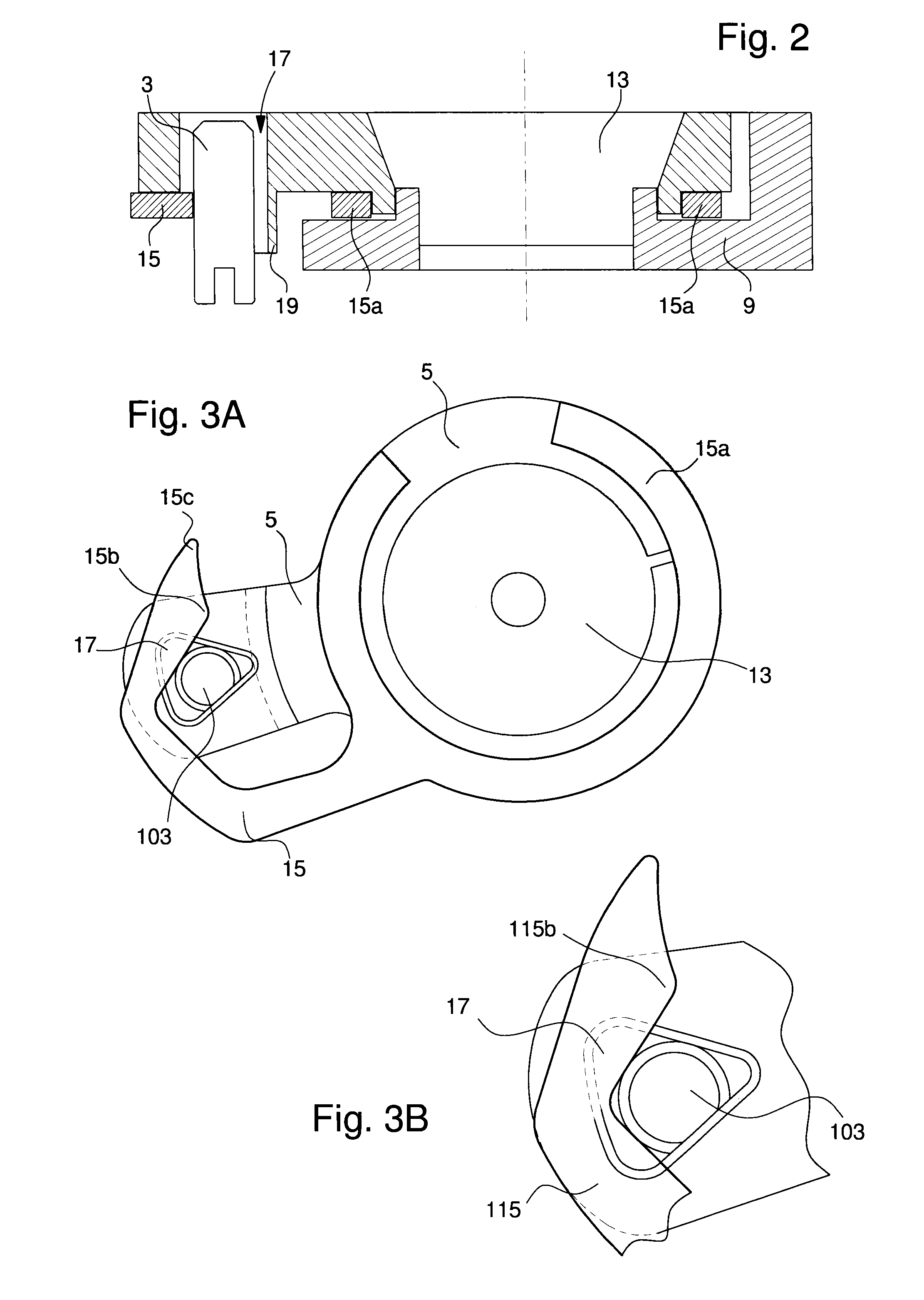
[0016]In the following description, the indications “top” and “bottom” refers to the cross-sectional view of FIG. 2. The bottom is the balance spring side. Further, the indication “turned outwards” is to be understood as meaning facing the opposite direction to the balance staff.

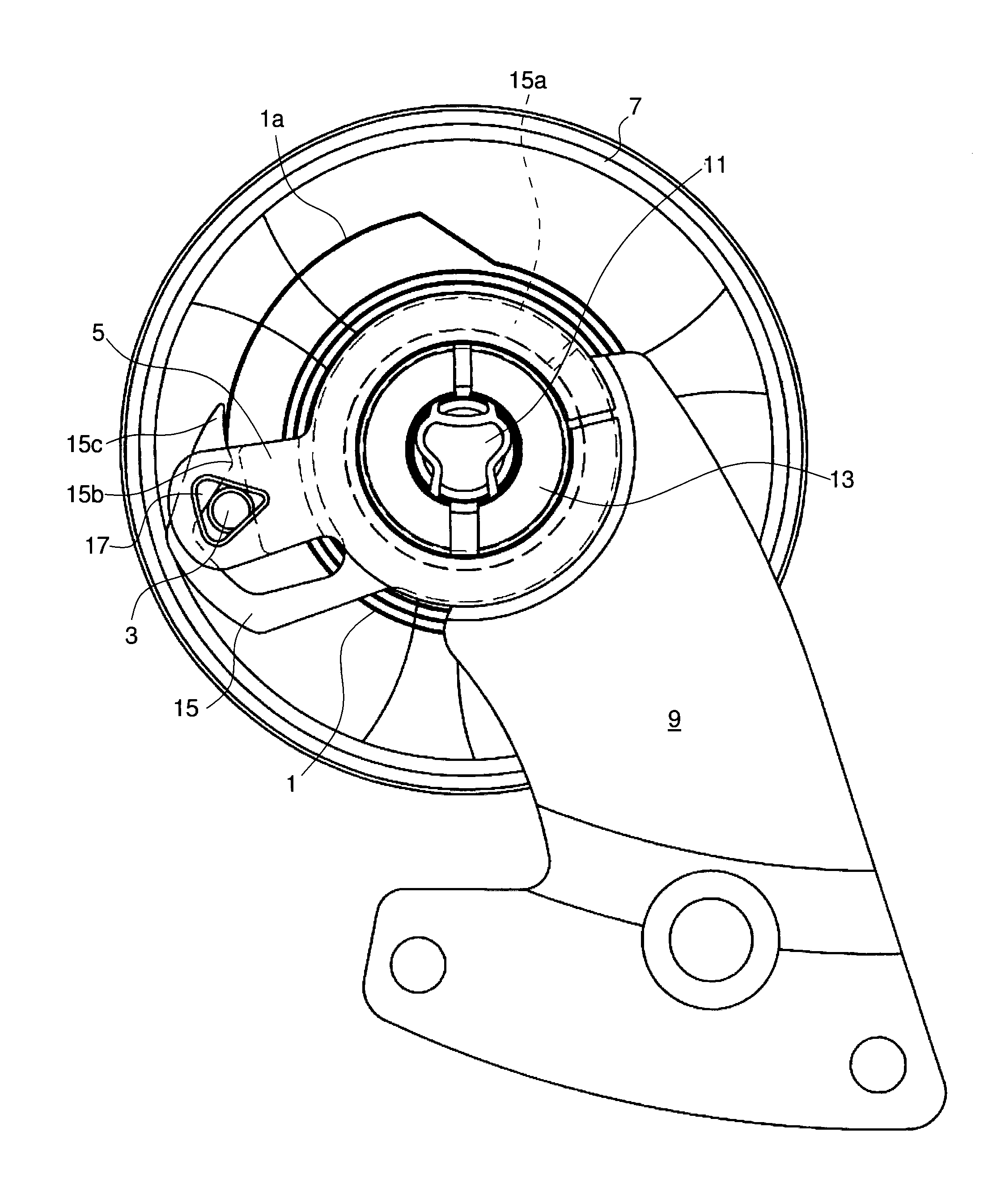
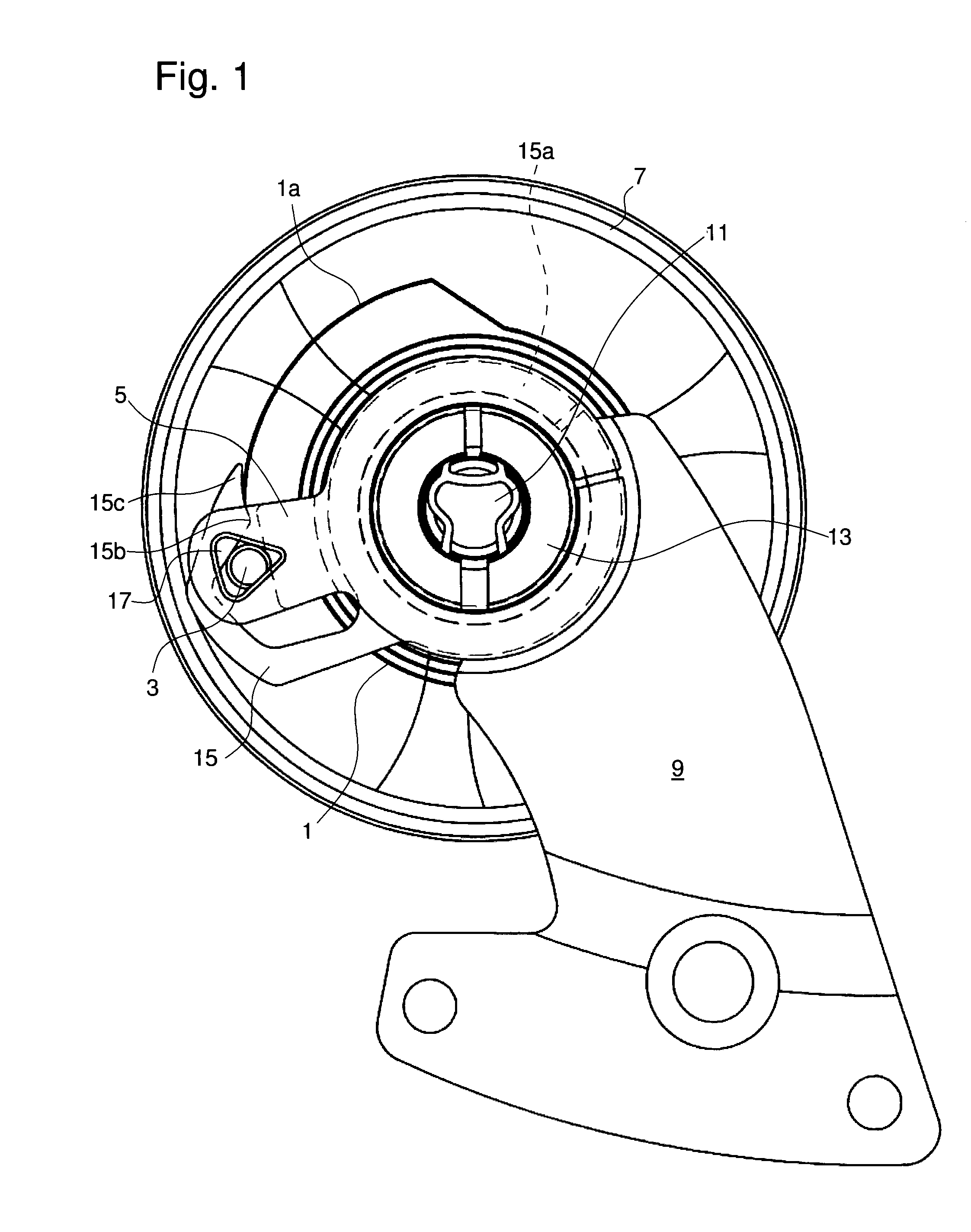
[0017]The Figures show a sprung balance regulating member for a timepiece corresponding to a particular embodiment of the invention. FIG. 1 shows the balance 7 whose staff is pivoted between two bearings. In a conventional manner, one of these bearings (referenced 11) is carried by the balance bridge (or cock) 9 via a top balance-endpiece 13, whereas the other bearing is mounted in the main plate (not shown). Also in a conventional manner, the balance is associated with a balance spring 1 whose central end is attached to the balance staff.

[0018]Cock 9 also serves as a support for an assembly formed by a stud 3, a stud holder 5 and an elastic arm 15. This assembly is intended to position the outer end 1a of b...


PUM


Abstract

The regulating device includes an inertial balance (7) including a balance staff arranged to be pivotally mounted in the timepiece, a balance bridge (9) and a bearing (11) carried by the balance bridge and arranged to hold one end of the balance staff, a balance spring (1) including an inner end integral with the balance and an outer end (1a) integral with a stud (3;103), and a mechanism for securing the stud (3; 103) including a housing (17) for receiving the stud and which is formed in a stud holder (5) pivoted on the balance bridge (9), the securing mechanism further including an elastic arm (15; 115) arranged to pivot concentrically to the balance staff between a first position where the elastic arm immobilises the stud (3; 103) and a second position where the elastic arm is disengaged from the stud to allow the stud to be inserted into or removed from the housing.

Description

[0001]This application claims priority from European Patent Application No. 13199179.6 filed 20 Dec. 2013, the entire disclosure of which is incorporated herein by reference.FIELD OF THE INVENTION[0002]The present invention concerns a regulating device for a timepiece including an inertial balance including a balance staff arranged to be pivotally mounted in the timepiece, a balance bridge carrying a bearing arranged to hold one end of the balance staff, a balance spring including an inner end integral with the balance and an outer end integral with a balance-spring stud, hereinafter “stud”, and finally a mechanism for securing the stud including a housing carried by the balance bridge and arranged to receive the stud whilst allowing the position thereof to be longitudinally adjusted, the securing mechanism further including an elastic arm arranged to bear laterally on the stud so as to immobilise the stud against a wall of the housing.PRIOR ART[0003]There are known regulating membe...

Claims


Application Information

Patent Timeline
IPC IPC(8): G04B15/14
CPCG04B17/32G04B15/14G04B18/06G04B17/325G04B17/06
Inventor CAPT, EDMOND
Owner BLANCPAIN SA
Learn More