Anti-Air-Return System and Method of Fan

Active Publication Date: 2015-06-04
DELTA ELECTRONICS INC
View PDF4 Cites 4 Cited by
  • Summary
  • Abstract
  • Description
  • Claims
  • Application Information

AI Technical Summary

Benefits of technology

The patent describes a way to prevent a fan from spinning backwards. This is done by detecting whether the fan is at an operation state or a standby state, and then stopping the motor if it is detected to be spinning backwards. This feature helps to ensure that the fan operates correctly and safely.

Problems solved by technology

However, if the heat generated by the electronic device can't be dissipated properly, the efficiency of the electronic device will be lowered down and the electronic device may be even damaged.
If the heat-dissipating fan is used under the condition of back pressure, it may be forced into a reverse rotation due to the generation of return air.
Hence, the heat-dissipating fan can't operate normally, thereby losing the heat-dissipating function.

Method used


Image

  • Anti-Air-Return System and Method of Fan
  • Anti-Air-Return System and Method of Fan
  • Anti-Air-Return System and Method of Fan

Examples


Embodiment Construction

[0039]The present invention will be apparent from the following detailed description, which proceeds with reference to the accompanying drawings, wherein the same references relate to the same elements.

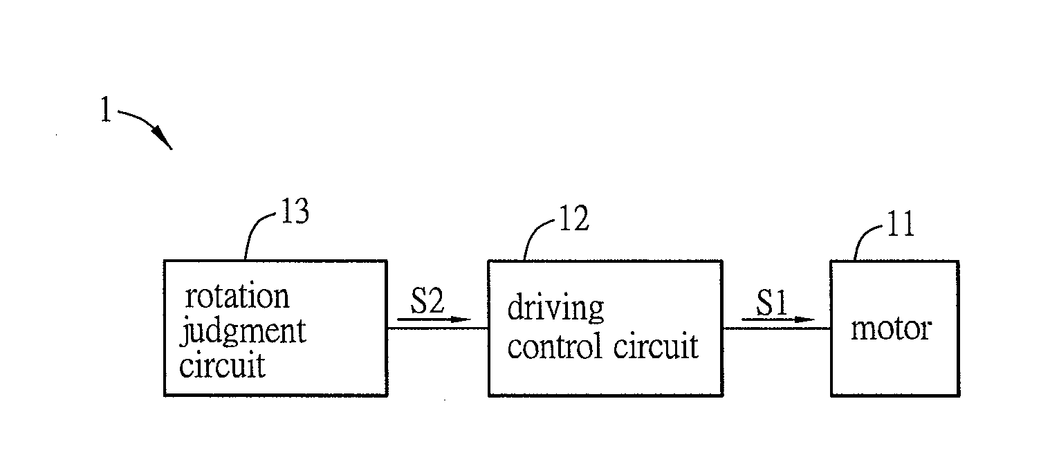
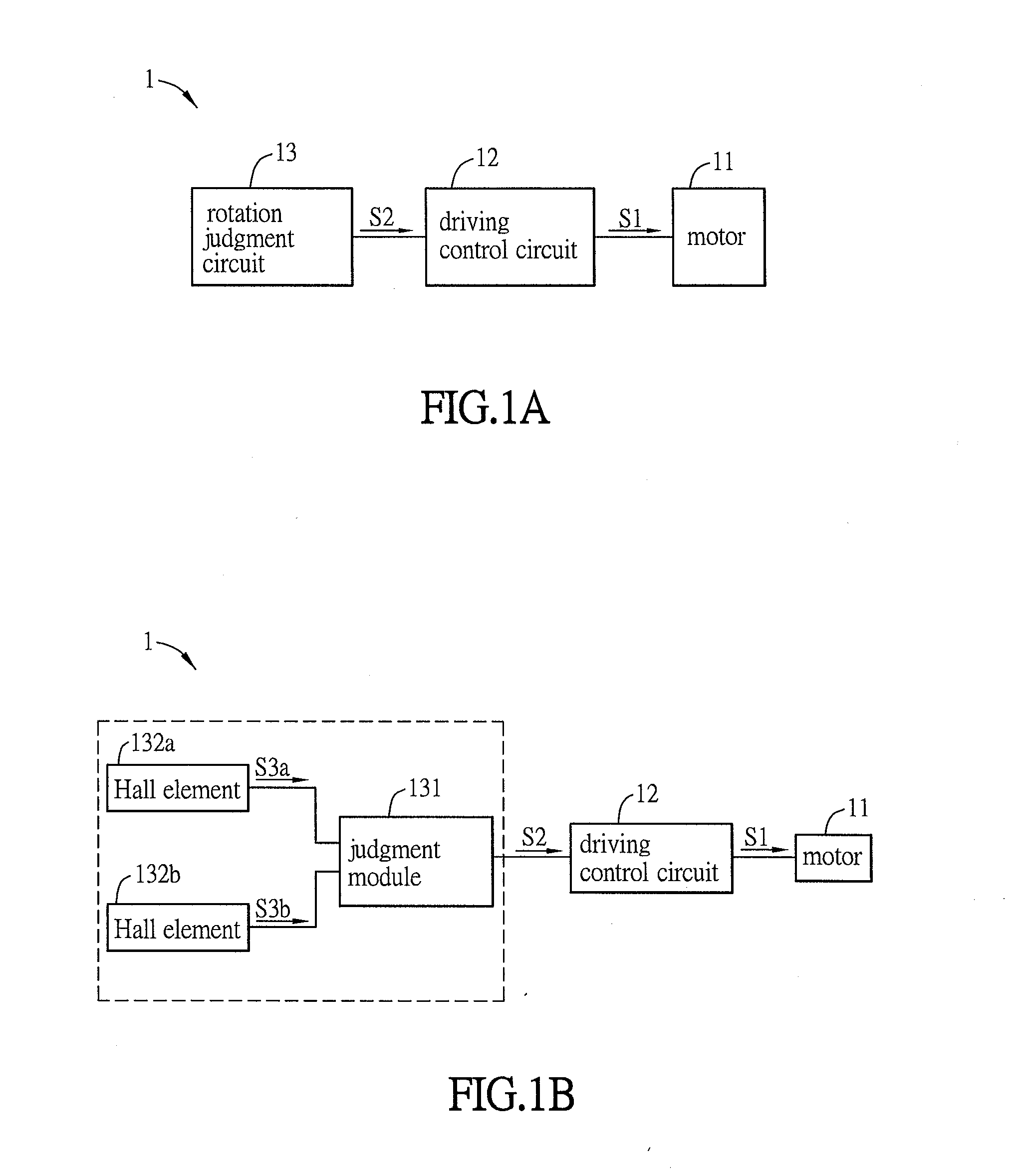
[0040]FIG. 1A is a schematic block diagram of an anti-air-return fan system according to an embodiment of the invention. As shown in FIG. 1, the anti-air-return fan system 1 includes a motor 11, a driving control circuit 12 and a rotation judgment circuit 13. In this embodiment, the motor 11 is connected to a fan to drive the impeller to rotate. The motor 11 can be a single-phase motor or a three-phase motor. The driving control circuit 12 is electrically connected to the motor 11. The driving control circuit 12 has a driving signal S1 for driving the motor 11 to rotate. The rotation judgment circuit 13 outputs a judgment signal S2 to the driving control circuit 12 when detecting that the motor 11 reversely rotate, and the driving control circuit 12 executes a braking according to the...


PUM


Abstract

An anti-air-return fan system includes a motor, a driving control circuit, and a rotation judgment circuit. The driving control circuit is electrically connected to the motor. The driving control circuit has a driving signal for driving the motor to rotate according to the driving signal. The rotation judgment circuit outputs a judgment signal to the driving control circuit when detecting that the motor reversely rotate. The driving control circuit executes a braking according to the judgment signal. The driving control circuit drives the motor to operate when the rotation judgment circuit detects that the motor doesn't rotate reversely.

Description

CROSS REFERENCE TO RELATED APPLICATIONS[0001]This Non-provisional application claims priority under 35 U.S.C. §119(a) on Patent Application No(s). 201310638549.9 filed in People's Republic of China on Nov. 29, 2013, the entire contents of which are hereby incorporated by reference.BACKGROUND OF THE INVENTION[0002]1. Field of Invention[0003]The invention relates to a fan system and, in particular, to an anti-air-return system and method of fan.[0004]2. Related Art[0005]With the progress of technologies, the efficiency of an electronic device is increasingly enhanced. However, if the heat generated by the electronic device can't be dissipated properly, the efficiency of the electronic device will be lowered down and the electronic device may be even damaged. Therefore, a heat-dissipating device becomes an indispensible appliance for the electronic device.[0006]Generally, the environment to which a heat-dissipating fan is applied is not always a free flow field. If the heat-dissipating...

Claims


Application Information

Patent Timeline
IPC IPC(8): F04D27/00F04D25/06
CPCF04D27/008F04D25/06F04D27/001F04D27/004
Inventor CHEN, JUNG-YUANCHEN, YEN-HUNGHSIEH, CHING-SENLIU, YUEH-HSINKAO, CHEN-CHIENCHIANG, SHIH-YUANLIN, JIAN-CUN
Owner DELTA ELECTRONICS INC
Why Eureka
Try Eureka