
System and method for shared surveillance

a technology of shared surveillance and surveillance information, applied in the field of shared surveillance, can solve the problems of ineffective communication of gathered surveillance information between multiple users, lack of widely-distributed collection systems and mechanisms, and inability of conventional surveillance systems to efficiently communicate gathered surveillance information to federal, state, and local agencies. the effect of strengthening a home, a business, and/or a nation

Inactive Publication Date: 2015-05-28
VOSE TECHN SYST
View PDF12 Cites 83 Cited by
  • Summary
  • Abstract
  • Description
  • Claims
  • Application Information

AI Technical Summary

Benefits of technology

The patent text explains that surveillance is a way to watch over people and gather information about their behavior. This can help in managing and controlling people, identifying threats, and preventing unwanted activities. Surveillance can be used at home, in businesses, in communities, and in nations, making it a crucial tool for strengthening these places.

Problems solved by technology

Although information can be gathered from multiple surveillance devices, systems lack an ability for this gathered surveillance information to be communicated between multiple users.
That is, many surveillance systems only allow the user to see their own personal surveillance environment and do not allow for a common picture showing surveillance data including images shared between multiple users.
Conventional surveillance systems also do not have an efficient way to communicate gathered surveillance information to federal, state, and local agencies, such as local law enforcement.
Communication problems stem from a lack of widely-distributed collection systems and mechanisms to rapidly organize incoming image and narrative data, evaluate the data, and communicate to interested parties.

Method used


Image

  • System and method for shared surveillance
  • System and method for shared surveillance
  • System and method for shared surveillance

Examples


Embodiment Construction

[0038]In the following description, for purposes of explanation and non-limitation, specific details are set forth, such as particular nodes, functional entities, techniques, protocols, etc. in order to provide an understanding of the described technology. It will be apparent to one skilled in the art that other embodiments may be practiced apart from the specific details described below. In other instances, detailed descriptions of well-known methods, devices, techniques, etc. are omitted so as not to obscure the description with unnecessary detail. Individual function blocks are shown in the figures. Those skilled in the art will appreciate that the functions of those blocks may be implemented using individual hardware circuits, using software programs and data in conjunction with a suitably programmed microprocessor or general purpose computer, using applications specific integrated circuitry (ASIC), and / or using one or more digital signal processors (DSPs). The software program ...


PUM


Abstract

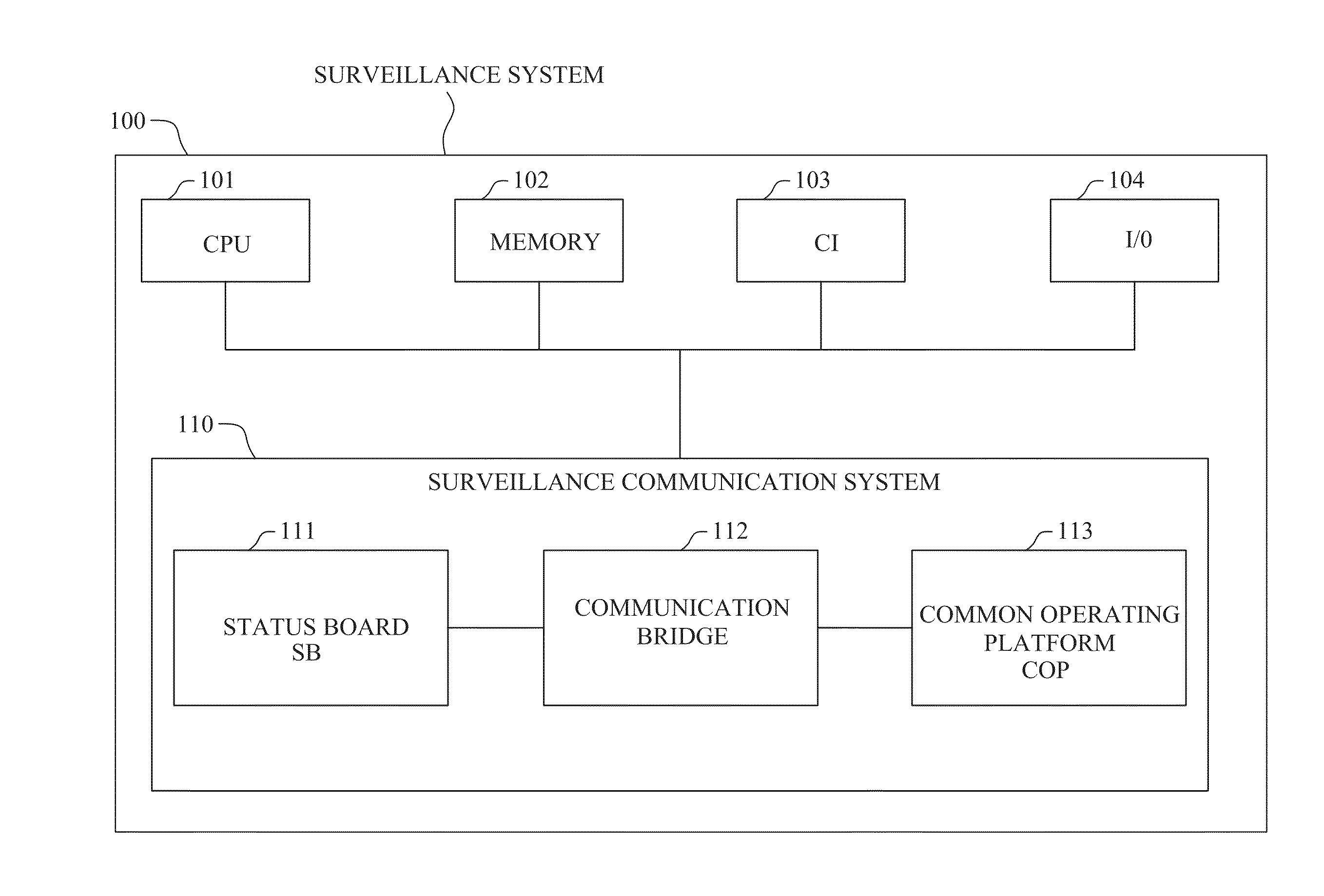
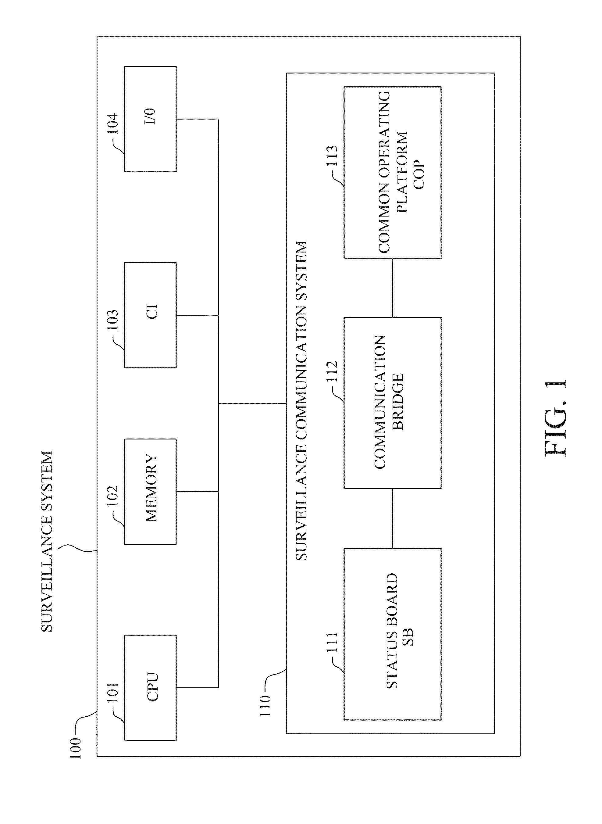
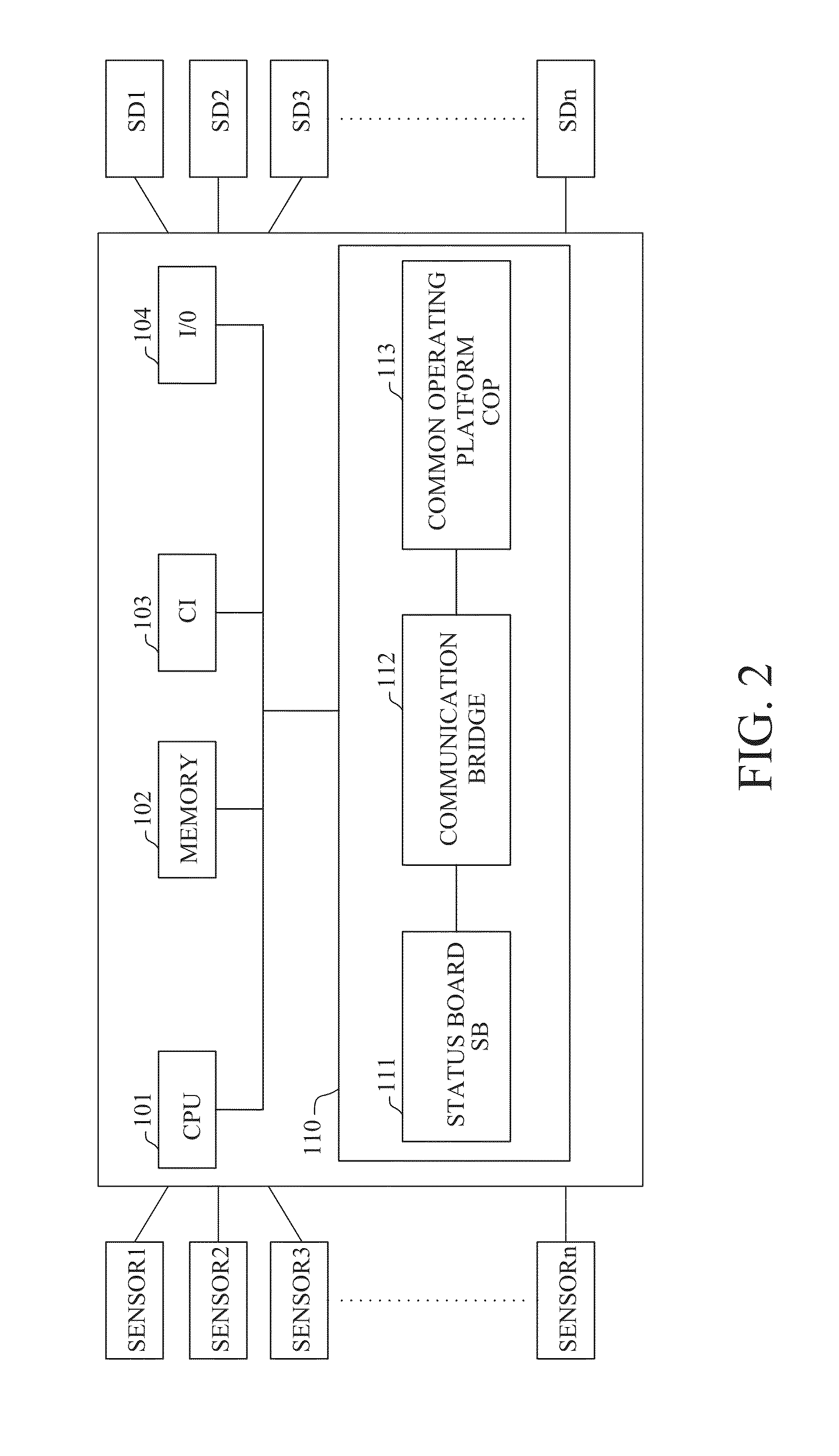
A common surveillance system allows multiple users to share and communicate surveillance data with each other as well as with one or more agencies, such as law enforcement, hospitals, and / or emergency services. A geo-reference database stores image data from imaging devices. A computer-implemented user interface accesses the geo-reference database to present stored image data on a display device. The user interface generates a status-board display, accessible to a specific client computer, showing images relating to a time and / or location of a display view imaged from the imaging devices. A common-operating platform shows images with a time and / or location associated with each image and is globally accessible to multiple client computers via one or more data communication networks. Based on a user input, images may be shared real-time via a bridge between the status-board display and the common-operating platform.

Description

CROSS-REFERENCE TO RELATED APPLICATIONS[0001]This application claims priority to U.S. Application No. 61 / 907,795, filed Nov. 22, 2013, the entire contents of which are incorporated herein by reference.BACKGROUND AND SUMMARY[0002]Surveillance means to “watch over” and includes the monitoring of the behavior, activities, or other changing information, usually of people for the purpose of influencing, managing, directing, or protecting people and / or resources. Surveillance is useful to maintain control, recognize and monitor threats, and prevent / investigate unwanted activity. Whether the surveillance is to enforce traffic laws, protect property, or even just see what is going on the front yard of someone's own home, surveillance can greatly strengthen a home, a business, a community, a town, and / or a nation.[0003]Conventional surveillance systems typically involve some type of image and / or audio recording device communicating with a system to store the recorded data and to let a user s...

Claims


Application Information

Patent Timeline
Patent Type & Authority Applications(United States)
IPC IPC(8): H04N7/18
CPCH04N7/181G06Q10/103G06Q30/04G06Q50/265G09B29/007
Inventor RUSSELL, JEFFREY W.VOSE, GREGORY A.
Owner VOSE TECHN SYST
Learn More