
Atomizing nozzle and electronic atomizing inhaler

a technology of electronic atomizing and atomizing nozzle, which is applied in the direction of tobacco, food science, and immersion heating arrangements, etc., can solve the problems of high manufacturing cost, difficult to assemble the above mentioned parts of the structure, and limited material for forming the liquid-draining mechanism, etc., to achieve convenient and safe use, simple structure, and easy assembly

Active Publication Date: 2015-05-28
SHENZHEN SMOORE TECH LTD
View PDF13 Cites 65 Cited by
  • Summary
  • Abstract
  • Description
  • Claims
  • Application Information

AI Technical Summary

Benefits of technology

The present invention aims to develop a better electronic atomizing product with a simple structure that is easy to assemble, convenient and safe to use. The main objective is to increase the volume of liquid being atomized to allow people to inhale easily and make it easy to assemble, store and use with a simple structure.

Problems solved by technology

Whilst the structure described above has a complicated structure and a high manufacturing cost, and it is difficult to assemble the above mentioned parts of the structure.
Although there is an improvement bases on the prior art, whilst just like the technical proposal disclosed in ZL200420031182.0, the heating apparatus is provided in the liquid-draining mechanism, resulting in the limitation of the material for forming the liquid-draining mechanism which needs to be hard, and the tendency of collapse of the liquid-draining mechanism during assembling.
Further, the liquid is also difficult to be transmitted from the liquid-draining mechanism to the secondary liquid-storage chamber.
In addition, the liquid volume possibility to be stored in the storage chamber is insufficient because of the storage chamber being made of medicinal cotton fibre.
The volume of the tobacco liquid in the insert part is totally depending on the absorbing of the liquid-storage medium, while the volume of the tobacco liquid being absorbed by the liquid-storage medium is insufficient.
In addition, it is difficult for the tobacco liquid deposited on the bottom of the atomizer to be drained out from the gas passage.

Method used


Image

  • Atomizing nozzle and electronic atomizing inhaler
  • Atomizing nozzle and electronic atomizing inhaler
  • Atomizing nozzle and electronic atomizing inhaler

Examples


Embodiment Construction

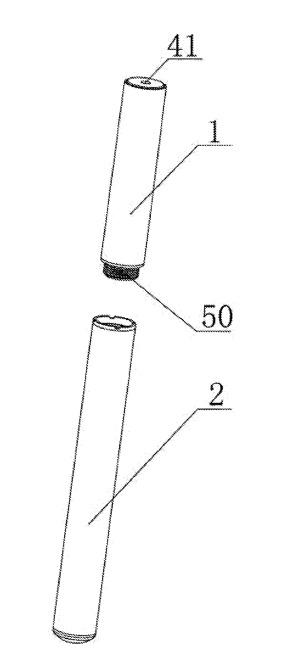
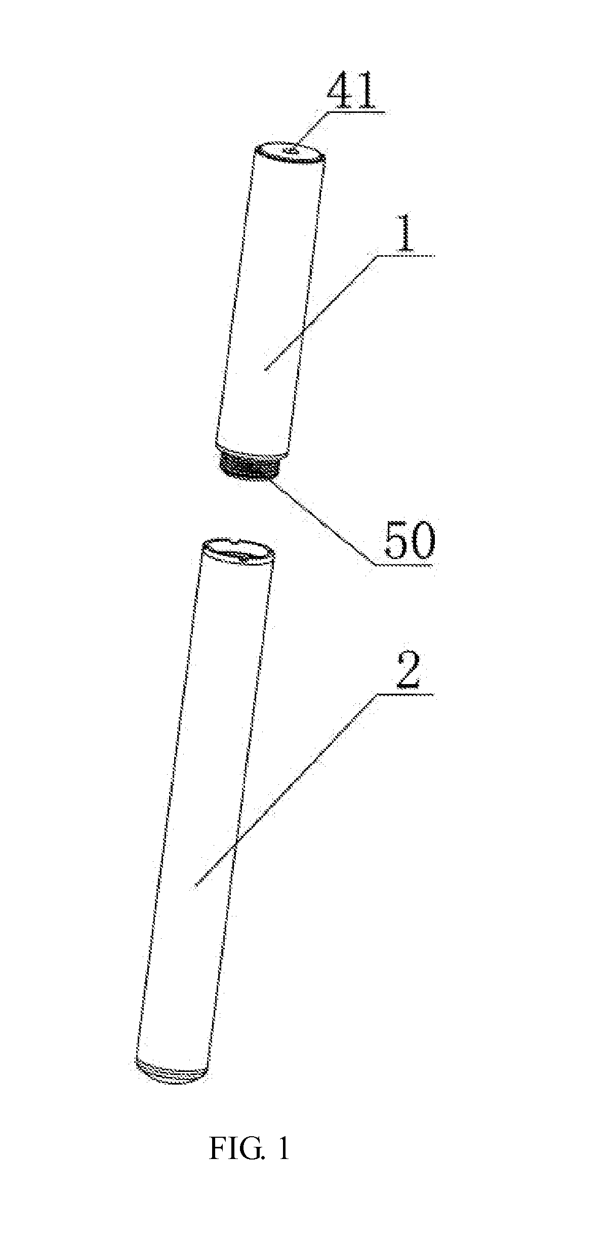
[0038]As shown in FIG. 1 of the drawings, the electronic atomizing inhaler is a kind of product for atomizing a liquid contained therein, so as to allow the consumer to inhale the atomized gas or fogged liquid therefrom. The inhaler comprises a cylindrical atomizing nozzle 1 and a cylindrical control and power portion 2, which are electrically and mechanically connected to each other by a screw-threaded electrode 50. The control and power portion 2 includes a power supply and a control circuit etc. The control and power portion 2 is arranged to apply electric power to the atomizing nozzle 1 and is detachably connected to the atomizing nozzle 1 by the screw-threaded electrode 50.

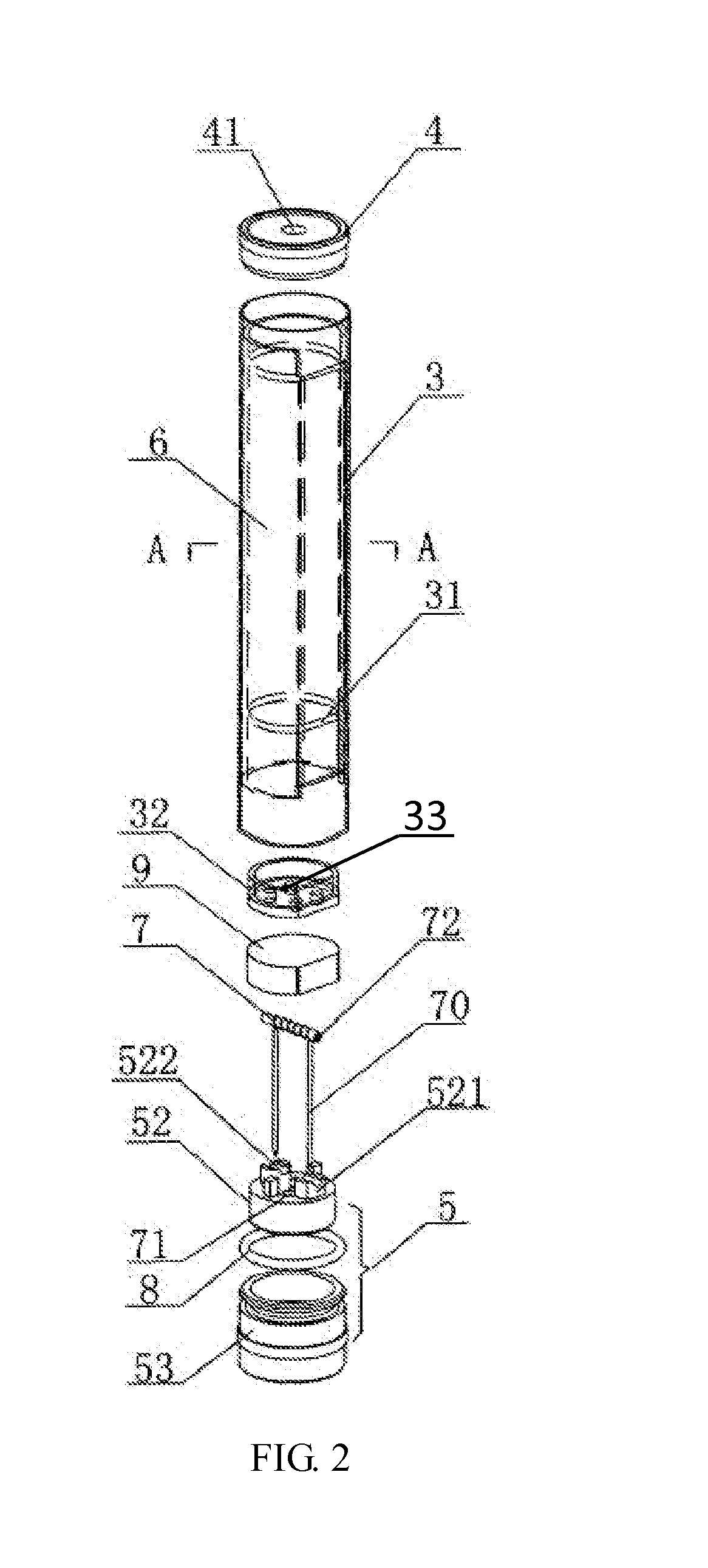
[0039]As shown in FIGS. 2 to 4 of the drawings, the atomizing nozzle 1 of the electronic atomizing inhaler comprises a tubular casing body 3.

[0040]A closure wall 4 is provided at the opening of the front end of the casing body 3. A gas-outlet aperture 41 is defined on the closure wall 4. The closure wall 4, l...


PUM


Abstract

An atomizing nozzle of an electronic atomizing inhaler, includes a casing body, provided with a cap at the opening of the front end, with a gas-outlet aperture on the cap, and provided with a rear closure at the opening of the rear end, with a gas-inlet aperture on the rear closure; a liquid-container and a heater provided in the cavity formed by the casing body, the cap and the rear closure, an airflow-passage being provided between the casing body and the liquid-container; a liquid-guiding device closing the mouth part of the liquid-container, with no liquid-storage medium provided in the liquid-container; and a heater provided on the top of the rear closure, contacting the lower surface of the liquid-guiding device. An electronic atomizing inhaler is also provided.

Description

REFERENCE TO RELATED APPLICATIONS[0001]This application is a continuation of U.S. application Ser. No. 13 / 824,335, filed on Sep. 21, 2013, now U.S. Pub. No. 2014 / 0007863, published Jan. 9, 2014, which is a national stage application under 35 U.S.C. 371 of PCT Application No. PCT / CN2012 / 000347 having an international filing date of Mar. 19, 2012, which designated the United States, which PCT application claimed the benefit of China Application No. 201110125093.7 filed May 12, 2011, the entire disclosure of each of which are incorporated herein by reference.FIELD OF THE INVENTION[0002]The present invention relates to an electronic atomizing apparatus which is used for atomizing an aromatic liquid for a user to inhale, and especially relates to an atomizing nozzle and an electronic atomizing inhaler having the atomizing nozzle.BACKGROUND OF THE INVENTION[0003]Electronic atomizers which yielding tobacco components or other materials in an inhalable form are normally used to substitute t...

Claims


Application Information

Patent Timeline
Patent Type & Authority Applications(United States)
IPC IPC(8): A24F47/00H05B3/80A24F40/10A24F40/42A24F40/44A24F40/485
CPCH05B3/80A24F47/008A24F40/10A24F40/44A24F40/42A24F40/485A24F40/48A24F40/46A61M11/042A61M11/00
Inventor CHEN, ZHIPING
Owner SHENZHEN SMOORE TECH LTD
Learn More