
Twist-lock button

a button and twisting technology, applied in the field of twisting buttons, can solve the problems of buttons falling off or breaking, shirts, tend to come undone, etc., and achieve the effects of being easy to use, durable, and secur

Active Publication Date: 2015-05-21
CAPITOL IND DESIGN LLC
View PDF7 Cites 3 Cited by
  • Summary
  • Abstract
  • Description
  • Claims
  • Application Information

AI Technical Summary

Benefits of technology

The present invention provides a durable, secure, and immune to jamming, twist lock fastener that is easy to use for people of varying abilities. The twist-lock button is made up of three distinct elements: a handle, a collar, and a negative. The handle rotates freely within the collar and can be twisted as much as required to achieve a secure friction fit. The handle has a grip portion and a locking portion, with the grip portion being easily manipulated to move the locking portion between a locked and an unlocked position. The exterior ridge on the negative interlocks with a corresponding ridge on the interior cavity, allowing for a secure friction fit. The handle can be rotated to enter into a locked position, with any number of rotations being possible.

Problems solved by technology

However, standard fasteners of the industry all have some kind of weakness that makes them less than ideal.
Snaps, although great for party shirts, tend to come undone under heavy loads and high winds.
Buttons pop off or break after prolonged use or in extreme conditions.
Zippers are notorious for jamming at the most inopportune moments.
And hook-and-loop fasteners tend to wear out over time.
In addition, standard fasteners are often difficult for people who have difficulty with fine motor skills.
Young children, stroke recoverees, people with cerebral palsy, ALS, Parkinson's disease, and amputees can find it difficult to manipulate buttons, snaps, zippers and Velcro.

Method used


Image

  • Twist-lock button
  • Twist-lock button
  • Twist-lock button

Examples


Embodiment Construction

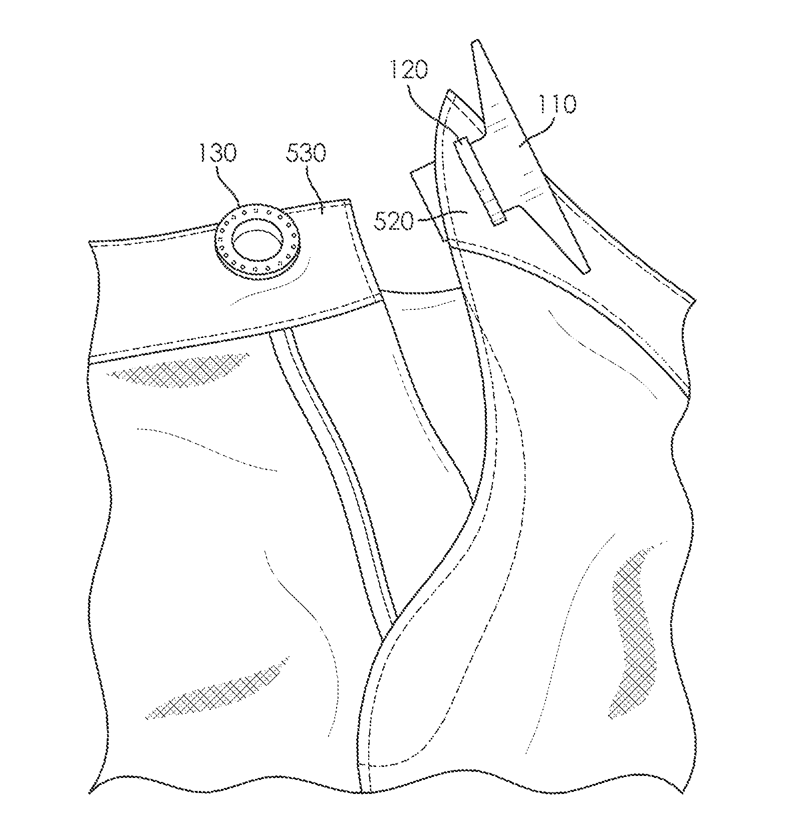
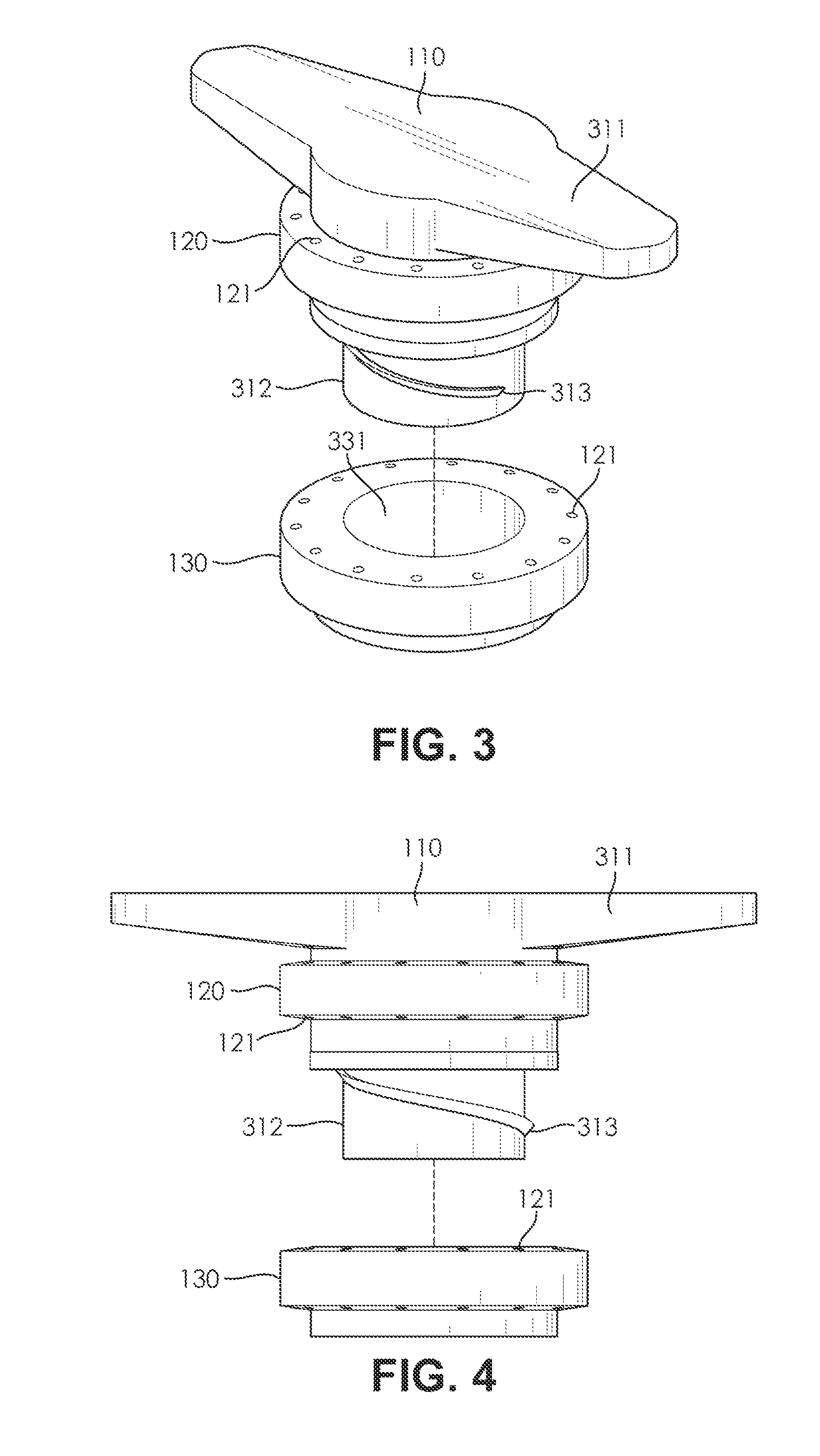
[0039]The present invention generally relates to fastening systems. Specifically, this invention relates to a twist-lock button configured to securely fasten two articles together. In preferred embodiments of the present invention, the twist-lock button comprises four pieces: a handle, a locking portion, a negative, and a button adapter. The negative attaches to an article by way of the button adapter. The locking portion attaches to the handle and passes through a button hole in the article to join with the negative, thereby fastening the two portions of the article together between the handle and the negative.

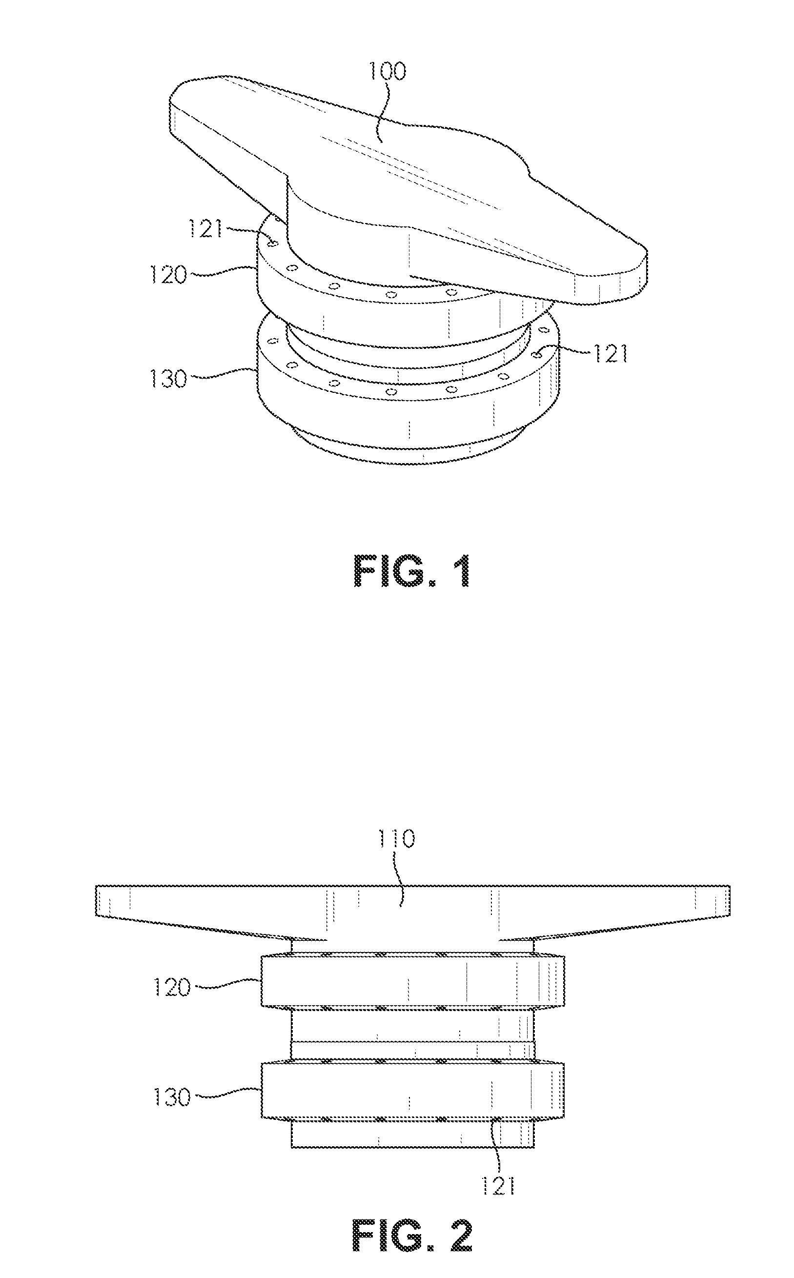
[0040]FIGS. 1-2 show views of the twist-lock button with the handle 110 engaged with both the collar 120 and the negative 130 in a locked position. FIG. 1 shows a perspective view of the twist-lock button and FIG. 2 shows a side view of the twist-lock button. According to an embodiment of the present invention shown in FIG. 1 and FIG. 2, the twist-lock button is comprised of ...


PUM


Abstract

The present invention generally relates to fastening systems. Specifically, this invention relates to a twist-lock button configured to securely fasten two articles together. In preferred embodiments of the present invention, the twist-lock button comprises four pieces: a handle, a locking portion, a negative, and a button adapter. The negative attaches to an article by way of the button adapter. The locking portion attaches to the handle and passes through a button hole in the article to join with the negative by twisting 180 degrees, thereby fastening the two portions of the article together between the handle and the negative. This mechanism is more durable than hook and loop fasteners, more reliable than buttons and snaps, and less prone to jamming than zippers. In addition, the twist-lock button is easier to use for people with muscular or motor disabilities, such as cerebral palsy, ALS, stroke recoverees, and amputees. These features and others will be detailed in greater depth within.

Description

FIELD OF THE INVENTION[0001]The present invention generally relates to fastening systems. Specifically, this invention relates to a twist-lock button configured to securely fasten two articles together. In preferred embodiments of the present invention, the twist-lock button comprises four pieces: a handle, a locking portion, a negative, and a button adapter. The negative attaches to an article by way of the button adapter. The locking portion attaches to the handle and passes through a button hole in the article to join with the negative, thereby fastening the two portions of the article together between the handle and the negative.BACKGROUND OF THE INVENTION[0002]Fasteners are an important part of sporting. Particularly in extreme applications, such as skiing, snowboarding, sailing, skydiving, bungee jumping, mountaineering, etc., having reliable fasteners for clothing and equipment can mean the difference between life and death. However, standard fasteners of the industry all hav...

Claims


Application Information

Patent Timeline
IPC IPC(8): A44B17/00A41F1/00
CPCA41F1/00A44B17/0064A44B1/30Y10T24/45089Y10T24/45257Y10T24/4578
Inventor BOLEN, ROBERT
Owner CAPITOL IND DESIGN LLC
Learn More